| Last Modified: 08-28-2024 | 6.11:8.1.0 | Doc ID: RM100000001900R |
| Model Year Start: 2018 | Model: Sienna | Prod Date Range: [11/2017 - ] |
| Title: NAVIGATION / MULTI INFO DISPLAY: NAVIGATION SYSTEM: AVC-LAN Circuit; 2018 - 2020 MY Sienna [11/2017 - ] | ||
|
AVC-LAN Circuit |
DESCRIPTION
Each unit of the navigation system connected to the AVC-LAN (communication bus) transmits signals via AVC-LAN communication.
If a short to +B or short to ground occurs in an AVC-LAN communication line, the navigation system will not function normally because communication is not possible.
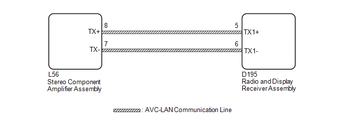
WIRING DIAGRAM
CAUTION / NOTICE / HINT
HINT:
The radio and display receiver assembly is the master unit.
NOTICE:
When replacing the radio and display receiver assembly, always replace it with a new one. If a radio and display receiver assembly which was installed to another vehicle is used, the following may occur:
- A communication malfunction DTC is stored.
- The radio and display receiver assembly may not operate normally.
PROCEDURE
|
1. |
INSPECT RADIO AND DISPLAY RECEIVER ASSEMBLY |
(a) Remove the radio and display receiver assembly.
Click here
![2018 - 2020 MY Sienna [11/2017 - ]; AUDIO / VIDEO: RADIO RECEIVER: REMOVAL](/t3Portal/stylegraphics/info.gif)
|
(b) Measure the resistance according to the value(s) in the table below. Standard Resistance:
|
|
| NG |

|
|

|
2. |
CHECK HARNESS AND CONNECTOR (AVC-LAN CIRCUIT) |
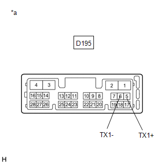
(a) Disconnect the D195 radio and display receiver assembly connector.
(b) Disconnect the L56 stereo component amplifier assembly connector.
(c) Measure the resistance according to the value(s) in the table below.
Standard Resistance:
|
Tester Connection |
Condition |
Specified Condition |
|---|---|---|
|
L56-8 (TX+) - D195-5 (TX1+) |
Always |
Below 1 Ω |
|
L56-7 (TX-) - D195-6 (TX1-) |
Always |
Below 1 Ω |
|
L56-8 (TX+) or D195-5 (TX1+) - Body ground |
Always |
10 kΩ or higher |
|
L56-7 (TX-) or D195-6 (TX1-) - Body ground |
Always |
10 kΩ or higher |
| NG |
|
REPAIR OR REPLACE HARNESS OR CONNECTOR |
|
|
3. |
INSPECT MALFUNCTIONING PARTS |
(a) Disconnect and reconnect each slave unit one by one until the master unit returns to normal.
HINT:
- Check all slave units.
- If disconnecting a slave unit causes the master unit to return to normal, the slave unit is defective and should be replaced.
OK:
Master unit returns to normal.
| OK |
|
REPLACE MALFUNCTIONING PARTS |
| NG |
|
|
|
|