| Last Modified: 08-28-2024 | 6.11:8.1.0 | Doc ID: RM1000000018YBL |
| Model Year Start: 2018 | Model: Sienna | Prod Date Range: [11/2017 - ] |
| Title: PRE-COLLISION: PRE-COLLISION SYSTEM: C1A4B; Stop Light Relay Circuit; 2018 - 2020 MY Sienna [11/2017 - ] | ||
|
DTC |
C1A4B |
Stop Light Relay Circuit |
DESCRIPTION
The skid control ECU (brake actuator assembly) sends a stop light operation request signal to the stop light relay (stop light switch assembly). If the skid control ECU (brake actuator assembly) detects a malfunction in the stop light relay circuit, the driving support ECU assembly stores DTC C1A4B.
|
DTC No. |
Detection Item |
DTC Detection Condition |
Trouble Area |
|---|---|---|---|
|
C1A4B |
Stop Light Relay Circuit |
Both of the following conditions are met:
HINT: The skid control ECU (brake actuator assembly) will detect a stop light relay circuit malfunction if any of the following conditions are met:
|
|
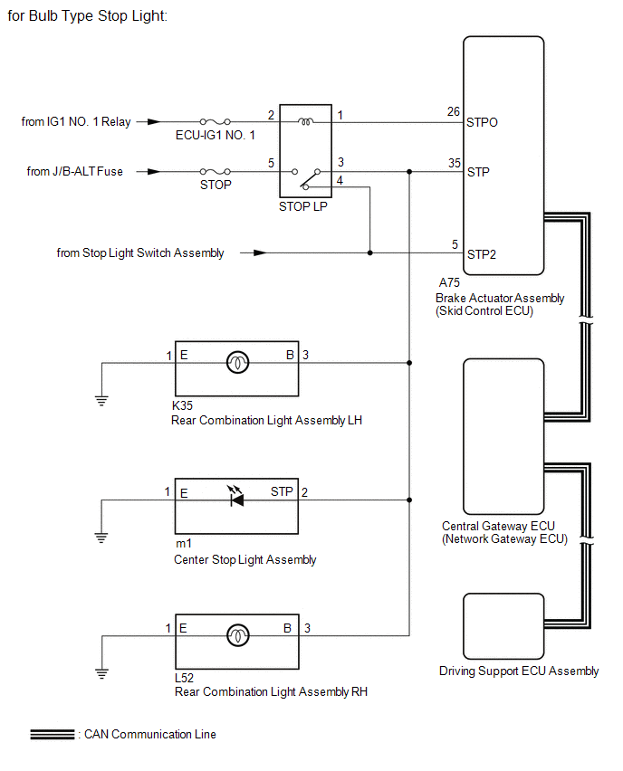
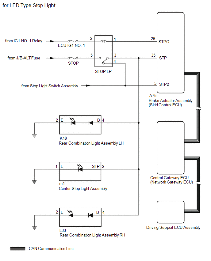
WIRING DIAGRAM
CAUTION / NOTICE / HINT
NOTICE:
- Inspect the fuses and bulbs*1 for circuits related to this system before performing the following procedure.
-
Perform the communication function inspections in Diagnosis System to confirm that there are no CAN communication malfunctions before performing the following procedure.
Click here
![2018 MY Sienna [11/2017 - 08/2018]; NETWORKING: CAN COMMUNICATION SYSTEM: DIAGNOSIS SYSTEM](/t3Portal/stylegraphics/info.gif)
- *1: for Bulb Type Stop Light
PROCEDURE
|
1. |
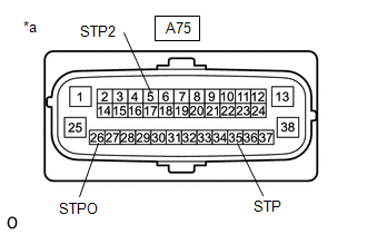
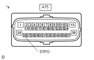
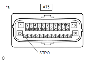
INSPECT TERMINAL VOLTAGE (SKID CONTROL ECU (BRAKE ACTUATOR ASSEMBLY) CONNECTOR) |
(a) Turn the ignition switch off.
|
(b) Disconnect the skid control ECU (brake actuator assembly) connector. |
|
(c) Measure the voltage according to the value(s) in the table below.
Standard Voltage:
|
Tester Connection |
Condition |
Specified Condition |
|---|---|---|
|
A75-5 (STP2) - Body ground |
Brake pedal depressed |
8 to 14 V |
|
Brake pedal released |
Below 1.5 V |
|
|
A75-26 (STPO) - Body ground |
Ignition switch ON |
11 to 14 V |
|
A75-35 (STP) - Body ground |
Brake pedal depressed |
8 to 14 V |
|
Brake pedal released |
Below 1.5 V |
(d) Connect the A75 skid control ECU (brake actuator assembly) connector.
|
Result |
Proceed to |
|---|---|
|
The voltage is as specified for every terminal. |
A |
|
Only the voltage at terminal STPO is not as specified. |
B |
|
Only the voltage at terminal STP is not as specified. |
C |
|
Only the voltage at terminal STP2 is not as specified. |
D |
|
The voltage at both terminal STPO and terminal STP are not as specified. |
E |
| B |

|
| C |
|
| D |
|
| E |
|
|

|
2. |
PERFORM ACTIVE TEST USING TECHSTREAM (STOP LIGHT RELAY) |
(a) Turn the ignition switch off.
(b) According to the display on the Techstream, perform the Active Test Stop Light Relay.
Click here
ABS/VSC/TRAC
|
Tester Display |
Test Part |
Control Range |
Diagnostic Note |
|---|---|---|---|
|
Stop Light Relay |
Stop light relay (Stop light switch assembly) |
ON/OFF |
Test possible at vehicle speed of 0 km/h (0 mph) |
OK:
The stop lights turn on and off correctly in response to the operation of the Active Test.
| NG |
|
|
|
3. |
CHECK FOR DTCS (PRE-COLLISION SYSTEM) |
(a) Clear the DTCs.
Click here
(b) According to the display on the Techstream, perform the Active Test Stop Light Relay.
Click here
ABS/VSC/TRAC
|
Tester Display |
Test Part |
Control Range |
Diagnostic Note |
|---|---|---|---|
|
Stop Light Relay |
Stop light relay (Stop light switch assembly) |
ON/OFF |
Test possible at vehicle speed of 0 km/h (0 mph) |
(c) Check for DTCs.
Click here
OK:
DTC C1A4B is not output.
| OK |
|
| NG |
|
|
4. |
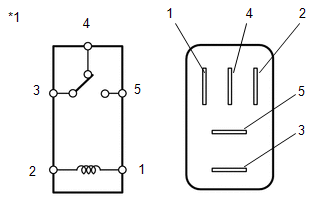
INSPECT STOP LP RELAY |
(a) Remove the STOP LP relay from No. 3 engine relay block.
|
(b) Measure the resistance according to the value(s) in the table below. Standard Voltage:
|
|
| OK |
|
| NG |
|
REPLACE STOP LP RELAY |
|
5. |
CHECK WIRE HARNESS AND CONNECTOR (BRAKE ACTUATOR ASSEMBLY (SKID CONTROL ECU) - STOP LIGHT LP RELAY) |
(a) Turn the ignition switch off.
|
(b) Remove the STOP LP relay from No. 3 engine room relay block. |
|

|
(c) Disconnect the A75 brake actuator assembly (skid control ECU) connector. |
|
(d) Measure the resistance according to the value(s) in the table below.
Standard Resistance:
|
Tester Connection |
Condition |
Specified Condition |
|---|---|---|
|
A75-26 (STPO) - Relay holder terminal 1 |
Always |
Below 1 Ω |
|
A75-26 (STPO) or Relay holder terminal 1 - Body ground |
Always |
10 kΩ or higher |
(e) Reconnect the A75 brake actuator assembly (skid control ECU) connector.
(f) Install the STOP LP relay to the No. 3 engine room relay block.
| NG |
|
REPAIR OR REPLACE HARNESS OR CONNECTOR |
|
|
6. |
INSPECT STOP LP RELAY (POWER SOURCE CIRCUIT) |
(a) Turn the ignition switch off.
|
(b) Remove the STOP LP relay from the No. 3 engine room relay block. |
|
(c) Measure the voltage according to the value(s) in the table below.
Standard Voltage:
|
Tester Connection |
Condition |
Specified Condition |
|---|---|---|
|
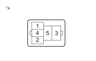
Relay holder terminal 2 - Body ground |
Ignition switch ON |
11 to 14 V |
|
Relay holder terminal 5 - Body ground |
Always |
11 to 14 V |
(d) Install the STOP LP relay to the No. 3 engine room relay block.
| OK |
|
REPLACE STOP LP RELAY |
| NG |
|
REPAIR OR REPLACE HARNESS OR CONNECTOR |
|
7. |
INSPECT STOP LP RELAY |
(a) Remove the STOP LP relay from No. 3 engine relay block.
|
(b) Measure the resistance according to the value(s) in the table below. Standard Voltage:
|
|
| NG |
|
REPLACE STOP LP RELAY |
|
|
8. |
CHECK WIRE HARNESS AND CONNECTOR (SKID CONTROL ECU (BRAKE ACTUATOR ASSEMBLY) - REAR COMBINATION LIGHT ASSEMBLY LH) |
(a) for Bulb Type Stop Light
(1) Turn the ignition switch off.
(2) Disconnect the A75 brake actuator assembly (skid control ECU) connector.
(3) Disconnect the K35 rear combination light assembly LH connector.
(4) Measure the voltage according to the value(s) in the table below.
Standard Voltage:
|
Tester Connection |
Condition |
Specified Condition |
|---|---|---|
|
A75-35 (STP) or K35-3 (B) - Body ground |
Brake pedal depressed |
8 to 14 V |
(5) Reconnect the K35 rear combination light assembly LH connector.
(6) Reconnect the A75 brake actuator assembly (skid control ECU) connector.
(b) for LED Type Stop Light
(1) Turn the ignition switch off.
(2) Disconnect the A75 brake actuator assembly (skid control ECU) connector.
(3) Disconnect the K18 rear combination light assembly LH connector.
(4) Measure the voltage according to the value(s) in the table below.
Standard Voltage:
|
Tester Connection |
Condition |
Specified Condition |
|---|---|---|
|
A75-35 (STP) or K18-4 (B) - Body ground |
Brake pedal depressed |
8 to 14 V |
(5) Reconnect the K18 rear combination light assembly LH connector.
(6) Reconnect the A75 brake actuator assembly (skid control ECU) connector.
| OK |
|
|
|
9. |
CHECK WIRE HARNESS AND CONNECTOR (SKID CONTROL ECU (BRAKE ACTUATOR ASSEMBLY) - CENTER STOP LIGHT ASSEMBLY) |
(a) Turn the ignition switch off.
(b) Disconnect the A75 skid control ECU (brake actuator assembly) connector.
(c) Disconnect the m1 center stop light assembly connector.
(d) Measure the voltage according to the value(s) in the table below.
Standard Voltage:
|
Tester Connection |
Condition |
Specified Condition |
|---|---|---|
|
A75-35 (STP) or m1-2 (STP) - Body ground |
Brake pedal depressed |
8 to 14 V |
(e) Connect the m1 center stop light assembly connector.
(f) Connect the A75 skid control ECU (brake actuator assembly) connector.
| OK |
|
|
|
10. |
CHECK WIRE HARNESS AND CONNECTOR (SKID CONTROL ECU (BRAKE ACTUATOR ASSEMBLY) - REAR COMBINATION LIGHT ASSEMBLY RH) |
(a) for Bulb Type Stop Light
(1) Turn the ignition switch off.
(2) Disconnect the A75 brake actuator assembly (skid control ECU) connector.
(3) Disconnect the L52 rear combination light assembly LH connector.
(4) Measure the voltage according to the value(s) in the table below.
Standard Voltage:
|
Tester Connection |
Condition |
Specified Condition |
|---|---|---|
|
A75-35 (STP) or L52-3 (B) - Body ground |
Brake pedal depressed |
8 to 14 V |
(5) Reconnect the L52 rear combination light assembly LH connector.
(6) Reconnect the A75 brake actuator assembly (skid control ECU) connector.
(b) for LED Type Stop Light
(1) Turn the ignition switch off.
(2) Disconnect the A75 brake actuator assembly (skid control ECU) connector.
(3) Disconnect the L33 rear combination light assembly LH connector.
(4) Measure the voltage according to the value(s) in the table below.
Standard Voltage:
|
Tester Connection |
Condition |
Specified Condition |
|---|---|---|
|
A75-35 (STP) or L33-4 (B) - Body ground |
Brake pedal depressed |
8 to 14 V |
(5) Reconnect the L33 rear combination light assembly LH connector.
(6) Reconnect the A75 brake actuator assembly (skid control ECU) connector.
| OK |
|
| NG |
|
REPAIR OR REPLACE HARNESS OR CONNECTOR |
|
11. |
INSPECT STOP LP RELAY |
(a) Remove the STOP LP relay from No. 3 engine relay block.
|
(b) Measure the resistance according to the value(s) in the table below. Standard Voltage:
|
|
| OK |
|
REPAIR OR REPLACE HARNESS OR CONNECTOR |
| NG |
|
REPLACE STOP LP RELAY |
|
12. |
CHECK WIRE HARNESS AND CONNECTOR (BRAKE ACTUATOR ASSEMBLY (SKID CONTROL ECU) - STOP LIGHT LP RELAY) |
(a) Turn the ignition switch off.
|
(b) Remove the STOP LP relay from No. 3 engine room relay block. |
|
|
(c) Disconnect the A75 brake actuator assembly (skid control ECU) connector. |
|
(d) Measure the resistance according to the value(s) in the table below.
Standard Resistance:
|
Tester Connection |
Condition |
Specified Condition |
|---|---|---|
|
A75-26 (STPO) - Relay holder terminal 1 |
Always |
Below 1 Ω |
(e) Reconnect the A75 brake actuator assembly (skid control ECU) connector.
(f) Install the STOP LP relay to the No. 3 engine room relay block.
| OK |
|
REPLACE STOP LP RELAY |
| NG |
|
REPAIR OR REPLACE HARNESS OR CONNECTOR |
|
|
|