| Last Modified: 08-28-2024 | 6.11:8.1.0 | Doc ID: RM1000000018YB3 |
| Model Year Start: 2018 | Model: Sienna | Prod Date Range: [11/2017 - ] |
| Title: PRE-COLLISION: PRE-COLLISION SYSTEM: TERMINALS OF ECU; 2018 - 2020 MY Sienna [11/2017 - ] | ||
TERMINALS OF ECU

CHECK DRIVING SUPPORT ECU ASSEMBLY
(a) Measure the voltage and resistance according to the value(s) in the table below.
|
Terminal No. (Symbol) |
Wiring Color |
Terminal Description |
Condition |
Specified Condition |
|---|---|---|---|---|
|
A80-7 (B) - A80-28 (GND) |
L - BR |
Power source |
Ignition switch ON |
11 to 14 V |
|
Ignition switch off |
Below 1 V |
|||
|
A80-3 (BZ) - A80-28 (GND) |
G - BR |
Skid control buzzer assembly output |
Ignition switch ON, buzzer not sounding |
11 to 14 V |
|
Ignition switch ON, buzzer sounding |
Below 1 V |
|||
|
A80-28 (GND) - Body ground |
BR - Body ground |
Ground |
Always |
Below 1 Ω |
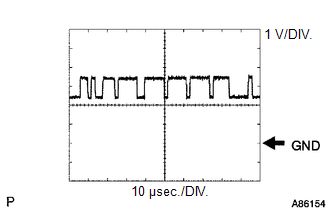
(b) Check for pulses according to the value(s) in the table below.
HINT:
If the waveform is not similar to that shown in the illustration, a malfunction of a CAN bus line, terminating resistor, or the driving support ECU assembly is suspected.
|
Terminal No. (Symbol) |
Wiring Color |
Terminal Description |
Condition |
Specified Condition |
|---|---|---|---|---|
|
A80-8 (CA1P) - A80-28 (GND) |
V - BR |
CAN communication signal |
Ignition switch ON |
Pulse generation (See waveform 1) |
|
A80-9 (CA1N) - A80-28 (GND) |
W - BR |
CAN communication signal |
Ignition switch ON |
Pulse generation (See waveform 2) |
|
A80-10 (CA2H) - A80-28 (GND) |
R - BR |
CAN communication signal |
Ignition switch ON |
Pulse generation (See waveform 1) |
|
A80-11 (CA2L) - A80-28 (GND) |
W - BR |
CAN communication signal |
Ignition switch ON |
Pulse generation (See waveform 2) |
(1) WAVEFORM 1
|
Item |
Content |
|---|---|
|
Terminal Name |
Between A80-8 (CA1P) - A80-28 (GND) Between A80-10 (CA2H) - A80-28 (GND) |
|
Tester Range |
1 V/DIV., 10 μsec./DIV. |
|
Condition |
Ignition switch ON |
HINT:
The waveform varies depending on the CAN communication signal.
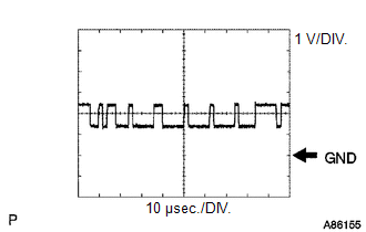
(2) WAVEFORM 2
|
Item |
Content |
|---|---|
|
Terminal Name |
Between A80-9 (CA1N) - A80-28 (GND) Between A80-11 (CA2L) - A80-28 (GND) |
|
Tester Range |
1 V/DIV., 10 μsec./DIV. |
|
Condition |
Ignition switch ON |
HINT:
The waveform varies depending on the CAN communication signal.

CHECK MILLIMETER WAVE RADAR SENSOR ASSEMBLY
(a) Measure the voltage and resistance according to the value(s) in the table below.
|
Terminal No. (Symbol) |
Wiring Color |
Terminal Description |
Condition |
Specified Condition |
|---|---|---|---|---|
|
A77-8 (IGB) - A77-1 (SGND) |
L - BR |
Power source |
Ignition switch ON |
11 to 14 V |
|
A77-1 (SGND) - Body ground |
BR - Body ground |
Ground |
Always |
Below 1 Ω |
(b) Check for pulses according to the value(s) in the table below.
HINT:
If the waveform is not similar to that shown in the illustration, a malfunction of a CAN bus line, terminating resistor, or the millimeter wave radar sensor assembly is suspected.
|
Terminal No. (Symbol) |
Wiring Color |
Terminal Description |
Condition |
Specified Condition |
|---|---|---|---|---|
|
A77-3 (CA2H) - A77-1 (SGND) |
GR - BR |
CAN communication signal |
Ignition switch ON |
Pulse generation (See waveform 1) |
|
A77-2 (CA2L) - A77-1 (SGND) |
W - BR |
CAN communication signal |
Ignition switch ON |
Pulse generation (See waveform 2) |
|
A77-5 (CA1P) - A77-1 (SGND) |
R - BR |
CAN communication signal |
Ignition switch ON |
Pulse generation (See waveform 1) |
|
A77-6 (CA1N) - A77-1 (SGND) |
W - BR |
CAN communication signal |
Ignition switch ON |
Pulse generation (See waveform 2) |
(1) WAVEFORM 1
|
Item |
Content |
|---|---|
|
Terminal Name |
Between A77-3 (CA2H) and A77-1 (SGND) Between A77-5 (CA1P) and A77-1 (SGND) |
|
Tester Range |
1 V/DIV., 10 μsec./DIV. |
|
Condition |
Ignition switch ON |
HINT:
The waveform varies depending on the CAN communication signal.
(2) WAVEFORM 2
|
Item |
Content |
|---|---|
|
Terminal Name |
Between A77-2 (CA2L) and A77-1 (SGND) Between A77-6 (CA1N) and A77-1 (SGND) |
|
Tester Range |
1 V/DIV., 10 μsec./DIV. |
|
Condition |
Ignition switch ON |
HINT:
The waveform varies depending on the CAN communication signal.
FORWARD RECOGNITION CAMERA
Click here
![2018 - 2020 MY Sienna [11/2017 - ]; CRUISE CONTROL: FORWARD RECOGNITION CAMERA SYSTEM: TERMINALS OF ECU](/t3Portal/stylegraphics/info.gif)
|
|
|