- Stop light switch
- Stop light switch circuit
- ECM
- Harness or connector
| Last Modified: 08-28-2024 | 6.11:8.1.0 | Doc ID: RM1000000018WRM |
| Model Year Start: 2018 | Model: Sienna | Prod Date Range: [11/2017 - ] |
| Title: CRUISE CONTROL: DYNAMIC RADAR CRUISE CONTROL SYSTEM: P057162; Brake Switch "A" Signal Compare Failure; 2018 - 2020 MY Sienna [11/2017 - ] | ||
|
DTC |
P057162 |
Brake Switch "A" Signal Compare Failure |
DESCRIPTION
The ECM receives the brake demand signal from the stop light switch assembly and transmits it to the skid control ECU (brake actuator assembly). The skid control ECU (brake actuator assembly) receives the signal from the ECM and operates the brake actuator.
|
DTC No. |
DTC Detection Condition |
Trouble Area |
MIL |
|---|---|---|---|
|
P057162 |
Voltage of STP terminal and that of ST1- terminal of ECM are less than 1 V for 0.5 seconds or more. |
|
Does not come on |
|
This trouble code is output when the ECM detects the stop light control relay error signal from the skid control ECU for 0.2 seconds or more while the dynamic cruise control is in operation. |
|
Does not come on |
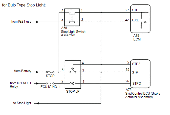
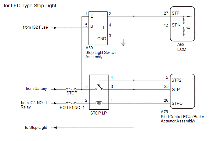
WIRING DIAGRAM
CAUTION / NOTICE / HINT
NOTICE:
Inspect the fuses for circuits related to this system before performing the following inspection procedure.
PROCEDURE
|
1. |
CHECK STOP LIGHT OPERATION |
(a) Check that the stop lights come on when the brake pedal is depressed, and go off when the brake pedal is released.
OK
|
Condition |
Illumination Condition |
|---|---|
|
Brake pedal depressed |
On |
|
Brake pedal released |
Off |
| NG |

|
|

|
2. |
READ VALUE USING TECHSTREAM (Cruise Brake Cancel Switch, Stop Light Switch Main-CPU, Stop Light Switch Sub-CPU) |
(a) Connect the Techstream to the DLC3.
(b) Turn the ignition switch to ON.
(c) Turn the Techstream on.
(d) Enter the following menus: Powertrain / Radar Cruise1 / Data List.
(e) Check the Data List for proper functioning of the stop light switch.
Radar Cruise1
|
Tester Display |
Measurement Item/Range |
Normal Condition |
Diagnostic Note |
|---|---|---|---|
|
Cruise Brake Cancel Switch |
Cruise control brake cancel condition/ ON or OFF |
ON: Brake pedal depressed OFF: Brake pedal released |
- |
|
Stop Light Switch Main-CPU |
Stop light switch signal/ ON or OFF |
ON: Brake pedal depressed OFF: Brake pedal released |
- |
|
Stop Light Switch Sub-CPU |
Stop light switch signal/ ON or OFF |
- |
This item is displayed on the Techstream but is not used. |
OK:
Display changes according to brake pedal operation described in the table.
|
Result |
Proceed to |
|---|---|
|
OK |
A |
|
NG (for Bulb Type Stop Light) |
B |
|
NG (for LED Type Stop Light) |
C |
| B |
|
| C |
|
|
|
3. |
CHECK HARNESS AND CONNECTOR (STOP LIGHT SWITCH ASSEMBLY - SKID CONTROL ECU (BRAKE ACTUATOR ASSEMBLY)) |
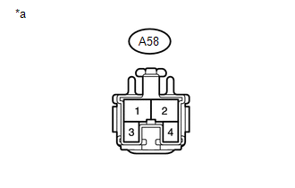
(a) Disconnect the A58 stop light switch assembly connector (for Bulb Type Stop Light).
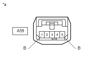
(b) Disconnect the A59 stop light switch assembly connector (for LED Type Stop Light).
(c) Disconnect the A75 skid control ECU (brake actuator assembly) connector.
(d) Measure the resistance according to the value(s) in the table below.
Standard Resistance (for Bulb Type Stop Light):
|
Tester Connection |
Condition |
Specified Condition |
|---|---|---|
|
A58-1 - A75-22 (STP2) |
Always |
Below 1 Ω |
|
A58-1 or A75-22 (STP2) - Body ground |
Always |
10 kΩ or higher |
Standard Resistance (for Bulb Type Stop Light):
|
Tester Connection |
Condition |
Specified Condition |
|---|---|---|
|
A59-2 (L) - A75-22 (STP2) |
Always |
Below 1 Ω |
|
A59-2 (L) or A75-22 (STP2) - Body ground |
Always |
10 kΩ or higher |
(e) Reconnect the A75 skid control ECU (brake actuator assembly) connector.
(f) Reconnect the A58 stop light switch assembly connector (for Bulb Type Stop Light).
(g) Reconnect the A59 stop light switch assembly connector (for LED Type Stop Light).
| NG |
|
REPAIR OR REPLACE HARNESS OR CONNECTOR |
|
|
4. |
CHECK HARNESS AND CONNECTOR (STOP LP RELAY - SKID CONTROL ECU (BRAKE ACTUATOR ASSEMBLY)) |
(a) Remove the STOP LP relay from the NO. 3 relay block.
(b) Disconnect the A75 skid control ECU (brake actuator assembly) connector.
(c) Measure the resistance according to the value(s) in the table below.
Standard Resistance:
|
Tester Connection |
Condition |
Specified Condition |
|---|---|---|
|
Relay terminal 1 - A75-31 (STPO) |
Always |
Below 1 Ω |
|
Relay terminal 4 - A75-22 (STP2) |
Always |
Below 1 Ω |
|
Relay terminal 3 - A75-2 (STP) |
Always |
Below 1 Ω |
|
Relay terminal 1 or A75-31 (STPO) - Body ground |
Always |
10 kΩ or higher |
|
Relay terminal 4 or A75-22 (STP2) - Body ground |
Always |
10 kΩ or higher |
|
Relay terminal 3 or A75-2 (STP) - Body ground |
Always |
10 kΩ or higher |
(d) Reinstall the STOP LP relay to the NO. 3 relay block.
(e) Reconnect the A75 skid control ECU (brake actuator assembly) connector.
| NG |
|
REPAIR OR REPLACE HARNESS OR CONNECTOR |
|
|
5. |
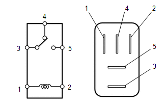
INSPECT STOP LP RELAY |
(a) Remove the STOP LP relay from the NO. 3 relay block.
|
(b) Measure the resistance according to the value(s) in the table below. Standard Resistance:
|
|
(c) Reinstall the STOP LP relay to the NO. 3 relay block.
| NG |
|
REPLACE STOP LP RELAY |
|
|
6. |
REPLACE BRAKE ACTUATOR ASSEMBLY (SKID CONTROL ECU) |
(a) Replace the skid control ECU (brake actuator assembly).
Click here
![2018 - 2020 MY Sienna [11/2017 - ]; BRAKE CONTROL / DYNAMIC CONTROL SYSTEMS: BRAKE ACTUATOR: REMOVAL](/t3Portal/stylegraphics/info.gif)
|
|
7. |
CHECK FOR DTCS (DTC P057162) |
(a) Connect the Techstream to the DLC3.
(b) Turn the ignition switch to ON.
(c) Clear the DTCs.
(d) Perform the following to make sure that the DTC detection conditions are met.
HINT:
If the detection conditions are not met, the malfunction cannot be detected.
- Drive the vehicle at a speed for which cruise control operation is possible.
- Turn the dynamic radar cruise control system on using the cruise control main switch (ON-OFF button).
- Push the cruise control main switch to -SET to activate the dynamic radar cruise control system.
(e) Enter the following menus: Powertrain / Radar Cruise1 / Trouble Codes.
(f) Check for DTCs.
Result
|
Result |
Proceed to |
|---|---|
|
DTCs are not output |
A |
|
DTC P057162 is output |
B |
(g) Turn the ignition switch off.
| A |
|
END |
| B |
|
|
8. |
CHECK HARNESS AND CONNECTOR (STOP LIGHT SWITCH ASSEMBLY - POWER SOURCE) |
(a) Disconnect the stop light switch assembly connector.
|
(b) Measure the voltage according to the value(s) in the table below. Standard Voltage:
Text in Illustration
|
|
(c) Reconnect the stop light switch assembly connector.
| NG |
|
REPAIR OR REPLACE HARNESS OR CONNECTOR |
|
|
9. |
INSPECT STOP LIGHT SWITCH ASSEMBLY |
(a) Remove the stop light switch assembly.
Click here
(b) Inspect the stop light switch assembly.
Click here
| NG |
|
|
|
10. |
CHECK HARNESS AND CONNECTOR (STOP LIGHT SWITCH ASSEMBLY - ECM) |
(a) Disconnect the A58 stop light switch assembly connector.
(b) Disconnect the A69 ECM connector.
(c) Measure the resistance according to the value(s) in the table below.
Standard Resistance:
|
Tester Connection |
Condition |
Specified Condition |
|---|---|---|
|
A58-3 - A69-42 (ST1-) |
Always |
Below 1 Ω |
|
A58-1 - A69-27 (STP) |
Always |
Below 1 Ω |
|
A58-3 or A69-42 (ST1-) - Body ground |
Always |
10 kΩ or higher |
|
A58-1 or A69-27 (STP) - Body ground |
Always |
10 kΩ or higher |
(d) Reconnect the A58 stop light switch assembly connector.
(e) Reconnect the A69 ECM connector.
| NG |
|
REPAIR OR REPLACE HARNESS OR CONNECTOR |
|
|
11. |
CHECK HARNESS AND CONNECTOR (STOP LIGHT SWITCH ASSEMBLY - BODY GROUND) |
(a) Disconnect the A58 stop light switch assembly connector.
(b) Measure the resistance according to the value(s) in the table below.
Standard Resistance:
|
Tester Connection |
Condition |
Specified Condition |
|---|---|---|
|
A58-1 - Body ground |
Always |
10 kΩ or higher |
|
A58-3 - Body ground |
Always |
10 kΩ or higher |
(c) Reconnect the A58 stop light switch assembly connector.
| OK |
|
| NG |
|
REPAIR OR REPLACE HARNESS OR CONNECTOR |
|
12. |
CHECK HARNESS AND CONNECTOR (STOP LIGHT SWITCH ASSEMBLY - POWER SOURCE) |
(a) Disconnect the stop light switch assembly connector.
|
(b) Measure the voltage according to the value(s) in the table below. Standard Voltage:
|
|
(c) Reconnect the stop light switch assembly connector.
| NG |
|
REPAIR OR REPLACE HARNESS OR CONNECTOR |
|
|
13. |
INSPECT STOP LIGHT SWITCH ASSEMBLY |
(a) Remove the stop light switch assembly.
Click here
(b) Inspect the stop light switch assembly.
Click here
| NG |
|
|
|
14. |
CHECK HARNESS AND CONNECTOR (STOP LIGHT SWITCH ASSEMBLY - ECM) |
(a) Disconnect the A59 stop light switch assembly connector.
(b) Disconnect the A69 ECM connector.
(c) Measure the resistance according to the value(s) in the table below.
Standard Resistance:
|
Tester Connection |
Condition |
Specified Condition |
|---|---|---|
|
A59-4 (L) - A69-42 (ST1-) |
Always |
Below 1 Ω |
|
A59-2 (L) - A69-27 (STP) |
Always |
Below 1 Ω |
|
A59-4 (L) or A69-42 (ST1-) - Body ground |
Always |
10 kΩ or higher |
|
A59-2 (L) or A69-27 (STP) - Body ground |
Always |
10 kΩ or higher |
(d) Reconnect the A59 stop light switch assembly connector.
(e) Reconnect the A69 ECM connector.
| NG |
|
REPAIR OR REPLACE HARNESS OR CONNECTOR |
|
|
15. |
CHECK HARNESS AND CONNECTOR (STOP LIGHT SWITCH ASSEMBLY - BODY GROUND) |
(a) Disconnect the A59 stop light switch assembly connector.
(b) Measure the resistance according to the value(s) in the table below.
Standard Resistance:
|
Tester Connection |
Condition |
Specified Condition |
|---|---|---|
|
A59-2 (L) - Body ground |
Always |
10 kΩ or higher |
|
A59-4 (L) - Body ground |
Always |
10 kΩ or higher |
(c) Reconnect the A59 stop light switch assembly connector.
| OK |
|
| NG |
|
REPAIR OR REPLACE HARNESS OR CONNECTOR |
|
|
|