| Last Modified: 08-28-2024 | 6.11:8.1.0 | Doc ID: RM1000000018KFD |
| Model Year Start: 2018 | Model: Sienna | Prod Date Range: [11/2017 - ] |
| Title: BRAKE CONTROL / DYNAMIC CONTROL SYSTEMS: VEHICLE STABILITY CONTROL SYSTEM: TS and CG Terminal Circuit; 2018 - 2020 MY Sienna [11/2017 - ] | ||
|
TS and CG Terminal Circuit |
DESCRIPTION
Connecting terminals TS and CG of the DLC3 causes the ECU to display Test Mode DTCs by blinking the ABS warning and slip indicator lights.
HINT:
TRAC OFF message is displayed on the multi-information display during Test Mode because TRAC is prohibited.
In Test Mode (signal check), a malfunction in a speed sensor that cannot be detected when the vehicle is stopped can be detected while driving.
Sensor check mode can be entered by connecting terminals TS and CG of the DLC3 and turning the ignition switch from off to ON.
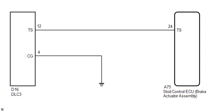
WIRING DIAGRAM
CAUTION / NOTICE / HINT
NOTICE:
When replacing the skid control ECU (brake actuator assembly), perform zero point calibration and store system information (See page
![2018 - 2020 MY Sienna [11/2017 - ]; BRAKE CONTROL / DYNAMIC CONTROL SYSTEMS: VEHICLE STABILITY CONTROL SYSTEM: CALIBRATION](/t3Portal/stylegraphics/info.gif) ).
).
PROCEDURE
|
1. |
CHECK HARNESS AND CONNECTOR (SKID CONTROL ECU - TS of DLC3) |
(a) Turn the ignition switch off.
(b) Disconnect the A75 skid control ECU (brake actuator assembly) connector.
(c) Measure the resistance according to the value(s) in the table below.
Standard Resistance:
|
Tester Connection |
Condition |
Specified Condition |
|---|---|---|
|
A75-24 (TS) - D16-12 (TS) |
Always |
Below 1 Ω |
|
A75-24 (TS) - Body ground |
Always |
10 kΩ or higher |
| NG |

|
REPAIR OR REPLACE HARNESS OR CONNECTOR |
|

|
2. |
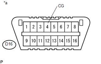
CHECK HARNESS AND CONNECTOR (CG of DLC3 - BODY GROUND) |
|
(a) Measure the resistance according to the value(s) in the table below. Standard Resistance:
Text in Illustration
|
|
| OK |
|
| NG |
|
REPAIR OR REPLACE HARNESS OR CONNECTOR |
|
|
|