| Last Modified: 08-28-2024 | 6.11:8.1.0 | Doc ID: RM1000000018KF8 |
| Model Year Start: 2018 | Model: Sienna | Prod Date Range: [11/2017 - ] |
| Title: BRAKE CONTROL / DYNAMIC CONTROL SYSTEMS: VEHICLE STABILITY CONTROL SYSTEM: Brake Warning Light Remains ON; 2018 - 2020 MY Sienna [11/2017 - ] | ||
|
Brake Warning Light Remains ON |
DESCRIPTION
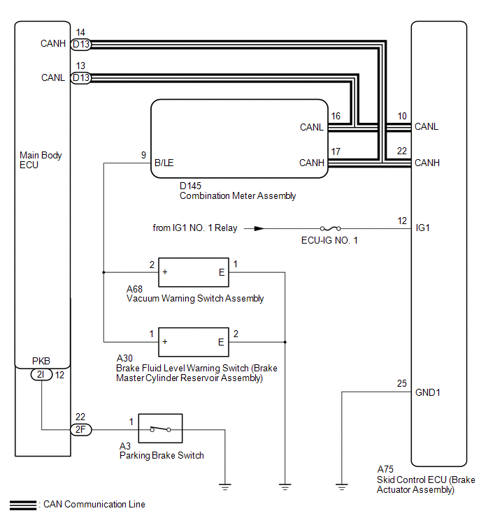
The skid control ECU (brake actuator assembly) is connected to the combination meter assembly via CAN communication.
If any of the following is detected, the brake warning light remains on:
- The skid control ECU (brake actuator assembly) connector is disconnected from the skid control ECU (brake actuator assembly).
- The brake fluid level is insufficient.
- EBD operation is not possible.
- The vacuum inside the brake booster decreases.
WIRING DIAGRAM
CAUTION / NOTICE / HINT
NOTICE:
-
When replacing the skid control ECU (brake actuator assembly), perform zero point calibration and store system information (See page
![2018 - 2020 MY Sienna [11/2017 - ]; BRAKE CONTROL / DYNAMIC CONTROL SYSTEMS: VEHICLE STABILITY CONTROL SYSTEM: CALIBRATION](/t3Portal/stylegraphics/info.gif) ).
).
-
If the main body ECU (multiplex network body ECU) is replaced, refer to Registration.
-
w/ Smart Key System:
(See page
). -
w/o Smart Key System:
(See page
).
-
w/ Smart Key System:
- Inspect the fuses for circuits related to this system before performing the following inspection procedure.
PROCEDURE
|
1. |
CHECK CAN COMMUNICATION SYSTEM |
(a) Check if CAN communication system DTCs are output (See page
).
|
Result |
Proceed to |
|---|---|
|
DTCs are not output. |
A |
|
DTCs are output. |
B |
| B |

|
|

|
2. |
CHECK IF BRAKE ACTUATOR ASSEMBLY CONNECTOR IS SECURELY CONNECTED |
(a) Check if the skid control ECU (brake actuator assembly) connector is securely connected.
OK:
The connector is securely connected.
| NG |
|
CONNECT CONNECTOR TO BRAKE ACTUATOR ASSEMBLY CORRECTLY |
|
|
3. |
INSPECT BATTERY POSITIVE TERMINAL |
(a) Check the battery voltage.
Standard Voltage:
11 to 14 V
| NG |
|
|
|
4. |
CHECK HARNESS AND CONNECTOR (IG1 TERMINAL) |
|
(a) Disconnect the skid control ECU (brake actuator assembly) connector. |
|
(b) Measure the voltage according to the value(s) in the table below.
Standard Voltage:
|
Tester Connection |
Switch Condition |
Specified Condition |
|---|---|---|
|
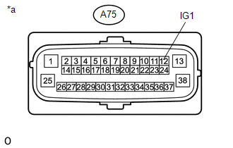
A75-12 (IG1) - Body ground |
Ignition switch ON |
10.5 to 16 V |
Text in Illustration
|
*a |
Front view of wire harness connector (to Skid Control ECU (Brake Actuator Assembly)) |
| NG |
|
REPAIR OR REPLACE HARNESS OR CONNECTOR (IG1 CIRCUIT) |
|
|
5. |
CHECK HARNESS AND CONNECTOR (GND1 TERMINAL) |
|
(a) Turn the ignition switch off. |
|
(b) Measure the resistance according to the value(s) in the table below.
Standard Resistance:
|
Tester Connection |
Condition |
Specified Condition |
|---|---|---|
|
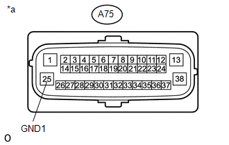
A75-25 (GND1) - Body ground |
Always |
Below 1 Ω |
Text in Illustration
|
*a |
Front view of wire harness connector (to Skid Control ECU (Brake Actuator Assembly)) |
| NG |
|
REPAIR OR REPLACE HARNESS OR CONNECTOR (GND1 CIRCUIT) |
|
|
6. |
READ VALUE USING TECHSTREAM (PARKING BRAKE SWITCH ASSEMBLY) |
(a) Reconnect the A75 skid control ECU (brake actuator assembly) connector.
(b) Connect the Techstream to the DLC3.
(c) Turn the ignition switch to ON.
(d) Turn the Techstream on.
(e) Enter the following menus: Chassis / ABS/VSC/TRAC / Data List.
(f) Select the Data List using the Techstream (See page
).
ABS/VSC/TRAC
|
Tester Display |
Measurement Item/Range |
Normal Condition |
Diagnostic Note |
|---|---|---|---|
|
Parking Brake SW |
Parking brake switch assembly / ON or OFF |
ON: Parking brake applied OFF: Parking brake released |
- |
(g) Using the Techstream, check the switch operation signal received when the parking brake is operated.
OK:
When the parking brake is operated, the display changes as shown above.
| NG |
|
|
|
7. |
INSPECT BRAKE FLUID LEVEL WARNING SWITCH (BRAKE MASTER CYLINDER RESERVOIR SUB-ASSEMBLY) |
|
(a) Turn the ignition switch off. |
|
(b) Remove the reservoir filler cap and strainer.
(c) Disconnect the A30 brake fluid level warning switch (brake master cylinder reservoir sub-assembly) connector.
(d) Measure the resistance according to the value(s) in the table below.
HINT:
A float is located inside the reservoir. Its position can be changed by increasing or decreasing the level of brake fluid.
Standard Resistance:
|
Tester Connection |
Condition |
Specified Condition |
|---|---|---|
|
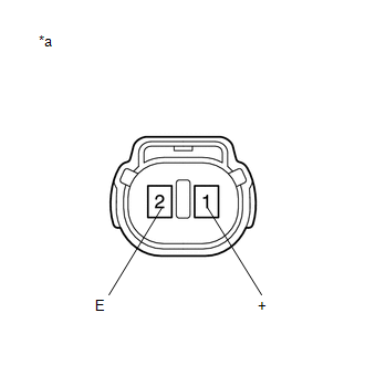
A30-1 (+) - A30-2 (E) |
Switch off (Float up) |
1.9 to 2.1 kΩ |
|
A30-1 (+) - A30-2 (E) |
Switch on (Float down) |
Below 1 Ω |
Text in Illustration
|
*a |
Component without harness connected (Brake Fluid Level Warning Switch (Brake Master Cylinder Reservoir Sub-assembly)) |
HINT:
If there is no problem after finishing the above check, adjust the brake fluid level to the MAX level.
| NG |
|
REPLACE BRAKE FLUID LEVEL WARNING SWITCH (BRAKE MASTER CYLINDER RESERVOIR SUB-ASSEMBLY) |
|
|
8. |
INSPECT VACUUM WARNING SWITCH ASSEMBLY |
(a) Inspect the vacuum warning switch assembly (See page
).
OK:
The vacuum warning switch assembly is normal.
| NG |
|
|
|
9. |
CHECK HARNESS AND CONNECTOR (COMBINATION METER ASSEMBLY - BRAKE MASTER CYLINDER RESERVOIR ASSEMBLY) |
(a) Disconnect the D145 combination meter assembly connector.
(b) Measure the resistance according to the value(s) in the table below.
Standard Resistance:
|
Tester Connection |
Condition |
Specified Condition |
|---|---|---|
|
D145-9 (B/LE) - A30-1 (+) |
Always |
Below 1 Ω |
|
D145-9 (B/LE) - Body ground |
Always |
10 kΩ or higher |
|
A30-2 (E) - Body ground |
Always |
Below 1 Ω |
|
D145-9 (B/LE) - A68-2 (+) |
Always |
Below 1 Ω |
|
A68-1 (E) - Body ground |
Always |
Below 1 Ω |
| NG |
|
REPAIR OR REPLACE HARNESS OR CONNECTOR |
|
|
10. |
READ VALUE USING TECHSTREAM (BRAKE WARNING LIGHT) |
(a) Reinstall the reservoir filler cap and strainer.
(b) Reconnect the D145 combination meter assembly connector and the A26 brake fluid level warning switch (brake master cylinder reservoir assembly) connector.
(c) Reconnect the A75 skid control ECU (brake actuator assembly) connector.
(d) Connect the Techstream to the DLC3.
(e) Turn the ignition switch to ON.
(f) Turn the Techstream on.
(g) Enter the following menus: Body Electrical / Combination Meter / Active Test.
(h) Select the Data List using the Techstream (See page
).
ABS/VSC/TRAC
|
Tester Display |
Measurement Item/Range |
Normal Condition |
Diagnostic Note |
|---|---|---|---|
|
Brake Warning Light |
Brake warning light / ON or OFF |
ON: Warning light on OFF: Warning light off |
- |
(i) Check the Techstream display condition of the brake warning light.
|
Result |
Proceed to |
|---|---|
|
Display of the Data List remains ON. |
A |
|
Display of the Data List remains OFF. |
B |
HINT:
If troubleshooting has been carried out according to Problem Symptoms Table, refer back to the table and proceed to the next step before replacing parts (See page
).
| A |
|
| B |
|
|
11. |
INSPECT PARKING BRAKE SWITCH ASSEMBLY |
|
(a) Turn the ignition switch off. |
|
(b) Disconnect the A3 parking brake switch assembly connector.
(c) Measure the resistance according to the value(s) in the table below.
Standard Resistance:
|
Tester Connection |
Condition |
Specified Condition |
|---|---|---|
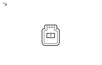
|
1 - Body ground |
Parking brake switch on (Switch pin free) |
Below 1 Ω |
|
1 - Body ground |
Parking brake switch off (Switch pin pushed in) |
10 kΩ or higher |
Text in Illustration
|
*a |
Component without harness connected (Parking Brake Switch Assembly) |
| NG |
|
|
|
12. |
CHECK HARNESS AND CONNECTOR (INSTRUMENT PANEL JUNCTION BLOCK - PARKING BRAKE SWITCH) |
(a) Disconnect the instrument panel junction block assembly connector.
(b) Measure the resistance according to the value(s) in the table below.
Standard Resistance:
|
Tester Connection |
Condition |
Specified Condition |
|---|---|---|
|
2F-22 - A3-1 |
Always |
Below 1 Ω |
|
2F-22 - Body ground |
Always |
10 kΩ or higher |
| NG |
|
REPAIR OR REPLACE HARNESS OR CONNECTOR |
|
|
13. |
CHECK HARNESS AND CONNECTOR (INSTRUMENT PANEL JUNCTION BLOCK - MAIN BODY ECU) |
(a) Remove the main body ECU from the instrument panel junction block assembly.
(b) Measure the resistance according to the value(s) in the table below.
Standard Resistance:
|
Tester Connection |
Condition |
Specified Condition |
|---|---|---|
|
2I-12 - 2F-22 |
Always |
Below 1 Ω |
|
2I-12 - Body ground |
Always |
10 kΩ or higher |
HINT:
If troubleshooting has been carried out according to Problem Symptoms Table, refer back to the table and proceed to the next step before replacing the part (See page
).
| OK |
|
| NG |
|
REPLACE INSTRUMENT PANEL JUNCTION BLOCK ASSEMBLY |
|
|
|