- Wire harness or connector
- Steering angle sensor (Spiral Cable with Sensor Sub-assembly)
| Last Modified: 08-28-2024 | 6.11:8.1.0 | Doc ID: RM1000000018KEW |
| Model Year Start: 2018 | Model: Sienna | Prod Date Range: [11/2017 - ] |
| Title: BRAKE CONTROL / DYNAMIC CONTROL SYSTEMS: VEHICLE STABILITY CONTROL SYSTEM: C1432; Steering Angle Sensor Power Source Voltage Malfunction; 2018 - 2020 MY Sienna [11/2017 - ] | ||
|
DTC |
C1432 |
Steering Angle Sensor Power Source Voltage Malfunction |
DESCRIPTION
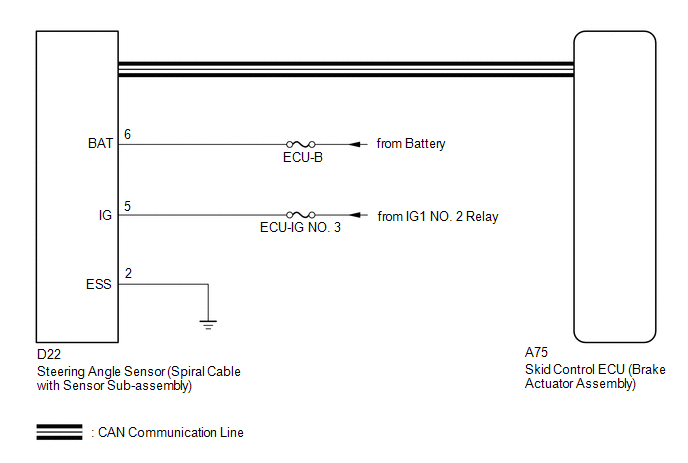
The skid control ECU (brake actuator assembly) outputs this DTC when it receives a sensor power source malfunction signal from the steering angle sensor (spiral cable with sensor sub-assembly).
|
DTC No. |
DTC Detection Condition |
Trouble Area |
|---|---|---|
|
C1432 |
Steering angle sensor power supply malfunction signal is received from steering angle sensor. |
|
WIRING DIAGRAM
CAUTION / NOTICE / HINT
NOTICE:
Inspect the fuses for circuits related to this system before performing the following inspection procedure.
HINT:
-
When U0073, U0124 and/or U0126 is output together with C1432, inspect and repair the trouble areas indicated by U0073, U0124 and/or U0126 first (See page
![2018 - 2020 MY Sienna [11/2017 - ]; BRAKE CONTROL / DYNAMIC CONTROL SYSTEMS: VEHICLE STABILITY CONTROL SYSTEM: U0073,U0100,U0124,U0126; Control Module Communication Bus OFF](/t3Portal/stylegraphics/info.gif) ).
).
- When the speed sensor or the yaw rate sensor (airbag sensor assembly) has trouble, DTCs for the steering angle sensor (spiral cable with sensor sub-assembly) may be output even when the steering angle sensor (spiral cable with sensor sub-assembly) is normal. When DTCs for the speed sensor or yaw rate sensor (airbag sensor assembly) are output together with DTCs for the steering angle sensor (spiral cable with sensor sub-assembly), inspect and repair the speed sensor and yaw rate sensor (airbag sensor assembly) first, and then inspect and repair the steering angle sensor (spiral cable with sensor sub-assembly).
PROCEDURE
|
1. |
CHECK HARNESS AND CONNECTOR (BAT TERMINAL) |
|
(a) Remove the steering wheel and the column cover. |
|
(b) Make sure that there is no looseness at the locking part and the connecting part of the connectors.
(c) Disconnect the steering angle sensor (spiral cable with sensor sub-assembly) connector.
(d) Measure the voltage according to the value(s) in the table below.
Standard Voltage:
|
Tester Connection |
Switch Condition |
Specified Condition |
|---|---|---|
|
D22-5 (IG) - Body ground |
Ignition switch ON |
11 to 14 V |
|
D22-6 (BAT) - Body ground |
Always |
11 to 14 V |
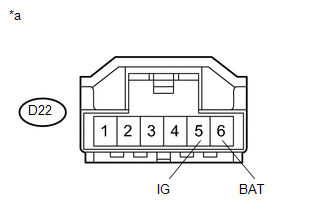
Text in Illustration
|
*a |
Front view of wire harness connector (to Steering Angle Sensor (Spiral Cable with Sensor Sub-assembly)) |
| NG |

|
REPAIR OR REPLACE HARNESS OR CONNECTOR (POWER SOURCE CIRCUIT) |
|

|
2. |
CHECK HARNESS AND CONNECTOR (ESS TERMINAL) |
|
(a) Turn the ignition switch off. |
|
(b) Measure the resistance according to the value(s) in the table below.
NOTICE:
Before measuring the resistance of the steering angle sensor (spiral cable with sensor sub-assembly), turn the ignition switch off and leave the vehicle for 1 minute or more without operating the key, switches or opening or closing the doors.
Standard Resistance:
|
Tester Connection |
Switch Condition |
Specified Condition |
|---|---|---|
|
D22-2 (ESS) - Body ground |
1 minute after ignition switch off |
Below 1 Ω |
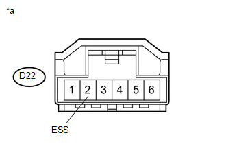
Text in Illustration
|
*a |
Front view of wire harness connector (to Steering Angle Sensor (Spiral Cable with Sensor Sub-assembly)) |
HINT:
If troubleshooting has been carried out according to Problem Symptoms Table, refer back to the table and proceed to the next step before replacing parts (See page
).
| OK |
|
REPLACE STEERING ANGLE SENSOR (SPIRAL CABLE WITH SENSOR SUB-ASSEMBLY) |
| NG |
|
REPAIR OR REPLACE HARNESS OR CONNECTOR (ESS CIRCUIT) |
|
|
|