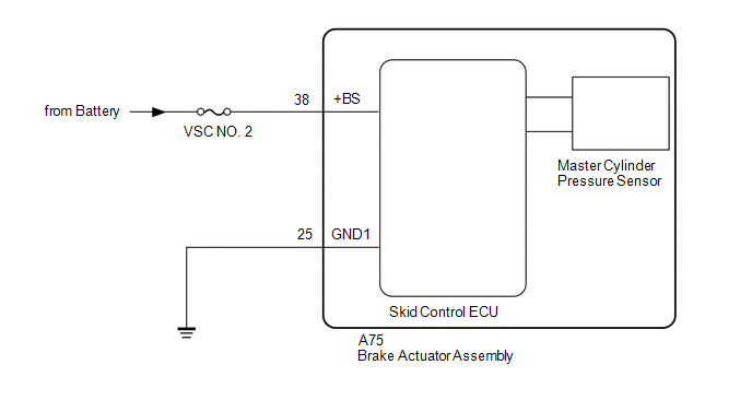
- The +BS terminal voltage is 17.4 V or more for 0.8 seconds or more.
- When voltage at terminal +BS is 17.4 V or higher, power supply voltage of master cylinder pressure sensor is cut for 0.2 seconds or more.
| Last Modified: 08-28-2024 | 6.11:8.1.0 | Doc ID: RM1000000018KEL |
| Model Year Start: 2018 | Model: Sienna | Prod Date Range: [11/2017 - ] |
| Title: BRAKE CONTROL / DYNAMIC CONTROL SYSTEMS: VEHICLE STABILITY CONTROL SYSTEM: C1417; High Power Supply Voltage Malfunction; 2018 - 2020 MY Sienna [11/2017 - ] | ||
|
DTC |
C1417 |
High Power Supply Voltage Malfunction |
DESCRIPTION
If a malfunction is detected in the power supply circuit, the skid control ECU (brake actuator assembly) stores this DTC and the fail-safe function prohibits ABS operation.
This DTC is stored when the +BS terminal voltage deviates from the DTC detection condition due to a malfunction in the power supply or charging circuit such as the battery or alternator circuit, etc.
The DTC is canceled when the +BS terminal voltage returns to normal.
|
DTC Code |
DTC Detection Condition |
Trouble Area |
|---|---|---|
|
C1417 |
Any of the following is detected: |
|
WIRING DIAGRAM
CAUTION / NOTICE / HINT
NOTICE:
-
When replacing the skid control ECU (brake actuator assembly), perform zero point calibration and store system information (See page
![2018 - 2020 MY Sienna [11/2017 - ]; BRAKE CONTROL / DYNAMIC CONTROL SYSTEMS: VEHICLE STABILITY CONTROL SYSTEM: CALIBRATION](/t3Portal/stylegraphics/info.gif) ).
).
- Inspect the fuses for circuits related to this system before performing the following inspection procedure.
PROCEDURE
|
1. |
INSPECT BATTERY |
(a) Check the battery voltage.
Standard Voltage:
11 to 14 V
| NG |

|
|

|
2. |
INSPECT SKID CONTROL ECU (+BS TERMINAL) |
|
(a) Make sure that there is no looseness at the locking part and the connecting part of the connectors. |
|
(b) Disconnect the skid control ECU (brake actuator assembly) connector.
(c) Turn the ignition switch to ON.
(d) Measure the voltage according to the value(s) in the table below.
Standard Voltage:
|
Tester Connection |
Switch Condition |
Specified Condition |
|---|---|---|
|
A75-38 (+BS) - Body ground |
Ignition switch ON |
11 to 14 V |
HINT:
If troubleshooting has been carried out according to Problem Symptoms Table, refer back to the table and proceed to the next step (See page
).
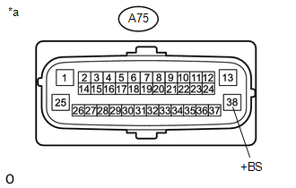
Text in Illustration
|
*a |
Front view of wire harness connector (to Skid Control ECU (Brake Actuator Assembly)) |
| NG |
|
REPAIR OR REPLACE HARNESS OR CONNECTOR (+BS CIRCUIT) |
|
|
3. |
RECONFIRM DTC |
(a) Turn the ignition switch off.
(b) Reconnect the A75 skid control ECU (brake actuator assembly) connector.
(c) Clear the DTCs (See page
).
(d) Turn the ignition switch off.
(e) Start the engine.
(f) Perform a road test.
(g) Check if the same DTC is output (See page
).
|
Result |
Proceed to |
|---|---|
|
DTC C1417 is not output. |
A |
|
DTC C1417 is output. |
B |
HINT:
If troubleshooting has been carried out according to Problem Symptoms Table, refer back to the table and proceed to the next step before replacing parts (See page
).
| A |
|
| B |
|
|
|
|