- Clear zero point calibration data and store system information.
- Perform yaw rate and acceleration sensor zero point calibration and store system information.
| Last Modified: 08-28-2024 | 6.11:8.1.0 | Doc ID: RM1000000018KDW |
| Model Year Start: 2018 | Model: Sienna | Prod Date Range: [11/2017 - ] |
| Title: BRAKE CONTROL / DYNAMIC CONTROL SYSTEMS: VEHICLE STABILITY CONTROL SYSTEM: CALIBRATION; 2018 - 2020 MY Sienna [11/2017 - ] | ||
CALIBRATION
1. DESCRIPTION
(a) After replacing any VSC related components or performing wheel alignment adjustment, clear and read the sensor calibration data and system information.
Refer to the table below and then perform the necessary operation according to the part to be replaced in order to perform calibration.
|
Parts to be Replaced / Operation |
Necessary Operation |
|---|---|
|
Skid control ECU (Brake actuator assembly) |
Perform yaw rate and acceleration sensor zero point calibration and store system information. |
|
Yaw rate and acceleration sensor (Airbag sensor assembly) |
|
|
Wheel alignment adjustment |
|
2. PERFORM YAW RATE AND ACCELERATION SENSOR ZERO POINT CALIBRATION AND STORE SYSTEM INFORMATION (When Using Techstream)
NOTICE:
- Stored system information cannot be overwritten unless it is cleared. Clear the stored information and then store new system information.
- While obtaining the zero points, keep the vehicle stationary and do not vibrate, tilt, move, or shake it (do not start the engine).
- Be sure to perform this procedure on a level surface (with an inclination of less than 1 degree).
- While obtaining the zero point, make sure the tire pressure is as specified and the vehicle is in full contact with the ground (not lifted up or loaded).
(a) Clear the zero point calibration data and store system information.
NOTICE:
Performing the following procedure will clear the zero points of the yaw rate and acceleration sensor and system information simultaneously.
(1) Turn the ignition switch off.
(2) Check that the steering wheel is centered.
(3) Check that the shift lever is in P.
(4) Connect the Techstream to the DLC3.
(5) Turn the ignition switch to ON.
(6) Turn the Techstream on.
(7) Select the skid control ECU (brake actuator assembly) to clear the zero point calibration data using the Techstream. Enter the following menus: Chassis / ABS/VSC/TRAC / Utility / Reset Memory.
(8) Turn the ignition switch off.
NOTICE:
If the ignition switch turned to ON for more than 15 seconds with the shift lever in P after the zero point of the yaw rate and acceleration sensor has been cleared, only the zero point of the yaw rate sensor will be stored. If the vehicle is driven under these conditions, the skid control ECU (brake actuator assembly) will store the zero point calibration for the acceleration sensor as not being completed. The skid control ECU (brake actuator assembly) will then also indicate this as a malfunction of the VSC system using the indicator light.
(b) Perform the yaw rate and acceleration sensor zero point calibration and store system information.
(1) Turn the ignition switch off.
(2) Check that the steering wheel is centered.
(3) Check that the shift lever is in P.
NOTICE:
- When Test Mode is selected with the shift lever not in P, the yaw rate and acceleration sensor zero point calibration incomplete DTC is stored.
- When the vehicle is driven with the zero point cleared, the yaw rate and acceleration sensor zero point calibration incomplete DTC is stored.
- If a DTC is stored that indicates zero point calibration is incomplete, repeat the procedure starting at the step for clearing the zero point calibration data and system information.
(4) Connect the Techstream to the DLC3.
(5) Turn the ignition switch to ON.
(6) Turn the Techstream on.
(7) Switch the skid control ECU (brake actuator assembly) to Test Mode using the Techstream. Enter the following menus: Chassis / ABS/VSC/TRAC / Utility / Test Mode.
(8) After Test Mode has been entered, keep the vehicle stationary on a level surface for 5 seconds or more.
(9) Check that the slip indicator light comes on for several seconds and then blinks in the Test Mode pattern.
HINT:
- If the slip indicator light does not blink, perform zero point calibration again.
- The zero point calibration is performed only once after the system enters the Test Mode.
- Calibration cannot be performed again until the stored data is cleared.
(10) Turn the ignition switch off and disconnect the Techstream.
3. PERFORM YAW RATE AND ACCELERATION SENSOR ZERO POINT CALIBRATION AND STORE SYSTEM INFORMATION (When not Using Techstream)
NOTICE:
- Stored system information cannot be overwritten unless it is cleared. Clear the stored information and then store new system information.
- While obtaining the zero points, keep the vehicle stationary and do not vibrate, tilt, move, or shake it (do not start the engine).
- Be sure to perform this procedure on a level surface (with an inclination of less than 1 degree).
- While obtaining the zero point, make sure the tire pressure is as specified and the vehicle is in full contact with the ground (not lifted up or loaded).
(a) Clear the zero point calibration data and store system information.
(1) Turn the ignition switch off.
(2) Check that the steering wheel is centered.
(3) Check that the shift lever is in P.
(4) Turn the ignition switch to ON.
(5) Using SST, connect and disconnect terminals 12 (TS) and 4 (CG) of the DLC3 4 times or more within 8 seconds.
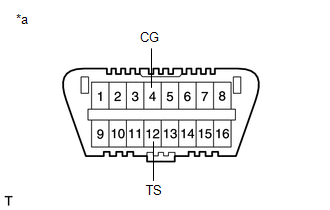
SST: 09843-18040
Text in Illustration
|
*a |
Front view of DLC3 |
(6) Check that the slip indicator light comes on.
NOTICE:
- If the vehicle is driven after the zero point of the yaw rate and acceleration sensor and system information are cleared, DTCs will be stored.
- If the ignition switch turned to ON for more than 15 seconds with the shift lever in P after the zero point of the yaw rate and acceleration sensor has been cleared, only the zero point of the yaw rate sensor will be stored. If the vehicle is driven under these conditions, the skid control ECU (brake actuator assembly) will store the zero point calibration for the acceleration sensor as not being completed. The skid control ECU (brake actuator assembly) will then also indicate this as a malfunction of the VSC system using the indicator light.
(7) Turn the ignition switch off.
(b) Perform the yaw rate and acceleration sensor zero point calibration and store system information.
NOTICE:
Performing the following procedure will perform the yaw rate and acceleration sensor zero point calibration, and also store system information simultaneously.
(1) Turn the ignition switch off.
(2) Check that the steering wheel is centered.
(3) Check that the shift lever is in P.
NOTICE:
- When Test Mode is selected with the shift lever not in P, the yaw rate and acceleration sensor zero point calibration incomplete DTC is stored.
- When the vehicle is driven with the zero point cleared, the yaw rate and acceleration sensor zero point calibration incomplete DTC is stored.
(4) Using SST, connect terminals 12 (TS) and 4 (CG) of the DLC3.
SST: 09843-18040
Text in Illustration
|
*a |
Front view of DLC3 |
(5) Turn the ignition switch to ON.
(6) After Test Mode has been entered, keep the vehicle stationary on a level surface for 5 seconds or more.
(7) Check that the slip indicator light comes on for several seconds and then blinks in the Test Mode pattern.
HINT:
- If the slip indicator light does not blink, perform zero point calibration again.
- The zero point calibration is performed only once after the system enters the Test Mode.
- Calibration cannot be performed again until the stored data is cleared.
(8) Turn the ignition switch off and disconnect SST from the DLC3.
|
|
|