| Last Modified: 08-28-2024 | 6.11:8.1.0 | Doc ID: RM1000000018K3Y |
| Model Year Start: 2018 | Model: Sienna | Prod Date Range: [11/2017 - ] |
| Title: CRUISE CONTROL: LANE DEPARTURE ALERT SYSTEM(w/ Steering Control): Steering Pad Switch Circuit; 2018 - 2020 MY Sienna [11/2017 - ] | ||
|
Steering Pad Switch Circuit |
DESCRIPTION
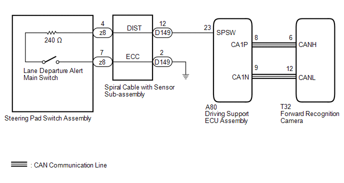
The driving support ECU assembly receives a lane departure alert switch signal from the steering pad switch assembly and sends the signal to the forward recognition camera via CAN communication.
WIRING DIAGRAM
w/ Steering Heater
w/o Steering Heater

CAUTION / NOTICE / HINT
NOTICE:
The vehicle is equipped with a Supplemental Restraint System (SRS) which includes components such as airbags. Before servicing (including removal or installation of parts), be sure to read the precaution for Supplemental Restraint System.
Click here
![2016 - 2020 MY Sienna [12/2015 - ]; SUPPLEMENTAL RESTRAINT SYSTEMS: AIRBAG SYSTEM: PRECAUTION](/t3Portal/stylegraphics/info.gif)
PROCEDURE
|
1. |
READ VALUE USING TECHSTREAM (CAN BUS CHECK) |
(a) Connect the Techstream to the DLC3.
(b) Turn the ignition switch to ON.
(c) Turn the Techstream on.
(d) Enter the following menus: System Select / CAN Bus Check.
|
Result |
Proceed to |
|---|---|
|
All of the ECUs and sensors that are currently connected to the CAN communication system are displayed |
A |
|
None of the ECUs and sensors that are currently connected to the CAN communication system are displayed, or some of them are not displayed |
B |
| B |

|
|

|
2. |
CHECK FOR DTCs (HEALTH CHECK) |
(a) Connect the Techstream to the DLC3.
(b) Turn the ignition switch to ON.
(c) Turn the Techstream on.
(d) Enter the following menus: System Select / Health Check.
(e) Check DTCs.
(f) Turn the ignition switch off.
|
Result |
Proceed to |
|---|---|
|
No DTCs are output. |
A |
|
DTCs are output. |
B |
| B |
|
GO TO DTC CHART |
|
|
3. |
INSPECT STEERING PAD SWITCH ASSEMBLY |
(a) Remove the steering pad switch assembly.
Click here
(b) Inspect the steering pad switch assembly.
Click here
| NG |
|
|
|
4. |
INSPECT SPIRAL CABLE WITH SENSOR SUB-ASSEMBLY |
(a) Remove the spiral cable with sensor sub-assembly.
Click here
(b) Inspect the spiral cable with sensor sub-assembly.
Click here
|
Result |
Proceed to |
|---|---|
|
OK (w/ Steering Heater) |
A |
|
OK (w/o Steering Heater) |
B |
|
NG |
C |
| B |
|
| C |
|
|
|
5. |
CHECK HARNESS AND CONNECTOR (SPIRAL CABLE WITH SENSOR SUB-ASSEMBLY - DRIVING SUPPORT ECU ASSEMBLY) |
(a) Disconnect the D149 spiral cable with sensor sub-assembly connector.
(b) Disconnect the A80 driving support ECU assembly connector.
(c) Measure the resistance according to the value(s) in the table below.
Standard Resistance (Check for Open):
|
Tester Connection |
Condition |
Specified Condition |
|---|---|---|
|
D149-12 (DIST) - A80-23 (SPSW) |
Always |
Below 1 Ω |
|
D149-2 (ECC) - Body ground |
Always |
Below 1 Ω |
Standard Resistance (Check for Short):
|
Tester Connection |
Condition |
Specified Condition |
|---|---|---|
|
D149-12 (DIST) or A80-23 (SPSW) - Body ground |
Always |
10 kΩ or higher |
(d) Connect the A80 driving support ECU assembly connector.
(e) Connect the D149 spiral cable with sensor sub-assembly connector.
| OK |
|
PROCEED TO NEXT SUSPECTED AREA SHOWN IN PROBLEM SYMPTOMS TABLE |
| NG |
|
REPAIR OR REPLACE HARNESS OR CONNECTOR |
|
6. |
CHECK HARNESS AND CONNECTOR (SPIRAL CABLE WITH SENSOR SUB-ASSEMBLY - DRIVING SUPPORT ECU ASSEMBLY) |
(a) Disconnect the D21 spiral cable with sensor sub-assembly connector.
(b) Disconnect the A80 driving support ECU assembly connector.
(c) Measure the resistance according to the value(s) in the table below.
Standard Resistance (Check for Open):
|
Tester Connection |
Condition |
Specified Condition |
|---|---|---|
|
D21-4 (DIST) - A80-23 (SPSW) |
Always |
Below 1 Ω |
|
D21-2 (ECC) - Body ground |
Always |
Below 1 Ω |
Standard Resistance (Check for Short):
|
Tester Connection |
Condition |
Specified Condition |
|---|---|---|
|
D21-4 (DIST) or A80-23 (SPSW) - Body ground |
Always |
10 kΩ or higher |
(d) Connect the A80 driving support ECU assembly connector.
(e) Connect the D21 spiral cable with sensor sub-assembly connector.
| OK |
|
PROCEED TO NEXT SUSPECTED AREA SHOWN IN PROBLEM SYMPTOMS TABLE |
| NG |
|
REPAIR OR REPLACE HARNESS OR CONNECTOR |
|
|
|