| Last Modified: 08-28-2024 | 6.11:8.1.0 | Doc ID: RM1000000018JBW |
| Model Year Start: 2018 | Model: Sienna | Prod Date Range: [11/2017 - ] |
| Title: PARK ASSIST / MONITORING: PARKING ASSIST MONITOR SYSTEM: Black Screen; 2018 - 2020 MY Sienna [11/2017 - ] | ||
|
Black Screen |
DESCRIPTION
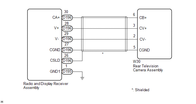
The video signal from the rear television camera assembly is transmitted to the radio and display receiver assembly.
WIRING DIAGRAM

CAUTION / NOTICE / HINT
NOTICE:
Depending on the parts that are replaced or operations that are performed during vehicle inspection or maintenance, calibration of other systems as well as the parking assist monitor system may be needed.
NOTICE:
-
When replacing the radio and display receiver assembly, always replace it with a new one. If a radio and display receiver assembly which was installed to another vehicle is used, the following may occurs:
- A communication malfunction DTC may be stored.
- The radio and display receiver assembly may not operate normally.
PROCEDURE
|
1. |
CHECK HARNESS AND CONNECTOR (RADIO AND DISPLAY RECEIVER ASSEMBLY - REAR TELEVISION CAMERA ASSEMBLY) |
(a) Disconnect the D196 radio and display receiver assembly connector.
(b) Disconnect the W30 rear television camera assembly connector.
(c) Measure the resistance according to the value(s) in the table below.
Standard Resistance:
|
Tester Connection |
Condition |
Specified Condition |
|---|---|---|
|
D196-30 (CA+) - W30-6 (CB+) |
Always |
Below 1 Ω |
|
D196-28 (V+) - W30-3 (CV+) |
Always |
Below 1 Ω |
|
D196-29 (V-) - W30-2 (CV-) |
Always |
Below 1 Ω |
|
D196-27 (CGND) - W30-5 (CGND) |
Always |
Below 1 Ω |
|
D196-26 (CSLD) - Body ground |
Always |
10 kΩ or higher |
|
D196-30 (CA+) or W30-6 (CB+) - Body ground |
Always |
10 kΩ or higher |
|
D196-28 (V+) or W30-3 (CV+) - Body ground |
Always |
10 kΩ or higher |
|
D196-29 (V-) or W30-2 (CV-) - Body ground |
Always |
10 kΩ or higher |
|
D196-27 (CGND) or W30-5 (CGND) - Body ground |
Always |
10 kΩ or higher |
| NG |

|
REPAIR OR REPLACE HARNESS OR CONNECTOR |
|
|
2. |
INSPECT RADIO AND DISPLAY RECEIVER ASSEMBLY |
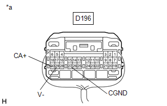
(a) Reconnect the radio and display receiver assembly connector.
|
(b) Measure the resistance according to the value(s) in the table below. Standard Resistance:
|
|
(c) Measure the voltage according to the value(s) in the table below.
Standard Voltage:
|
Tester Connection |
Condition |
Specified Condition |
|---|---|---|
|
D196-30 (CA+) - D196-27 (CGND) |
Engine switch on (ACC) |
5.5 to 7.05 V |
| NG |

|
|
|
3. |
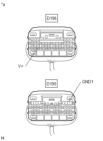
INSPECT RADIO AND DISPLAY RECEIVER ASSEMBLY (V+, GND1) |
|
(a) Reconnect the W30 rear television camera assembly connector. |
|
|
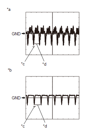
(b) Using an oscilloscope, check the waveform of the rear television camera assembly. HINT: A waterproof connector is used for the rear television camera assembly. Therefore, inspect the waveform at the radio and display receiver assembly with the connector connected. OK: Waveform is similar to that shown in the illustration.
HINT:
|
|
| NG |

|
|
|
4. |
REPLACE RADIO AND DISPLAY RECEIVER ASSEMBLY |
(a) Replace the radio and display receiver assembly with a new or known good one.
(b) Check that the parking assist monitor system operates normally.
OK:
Parking assist monitor system operates normally.
| OK |

|
END |
| NG |

|
|
|
|
![2018 - 2020 MY Sienna [11/2017 - ]; PARK ASSIST / MONITORING: PARKING ASSIST MONITOR SYSTEM: CALIBRATION](/t3Portal/stylegraphics/info.gif)


