- Speakers
- Harness or connector
- Radio and display receiver assembly*1
- Stereo component amplifier assembly*2
- DCM (telematics transceiver)*3
| Last Modified: 08-28-2024 | 6.11:8.1.0 | Doc ID: RM1000000018F7N |
| Model Year Start: 2018 | Model: Sienna | Prod Date Range: [11/2017 - ] |
| Title: AUDIO / VIDEO: AUDIO AND VISUAL SYSTEM: B15C3; Speaker Output Short; 2018 - 2020 MY Sienna [11/2017 - ] | ||
|
DTC |
B15C3 |
Speaker Output Short |
DESCRIPTION
This DTC is stored when a malfunction occurs in the speakers.
|
DTC Code |
DTC Detection Condition |
Trouble Area |
|---|---|---|
|
B15C3 |
A short is detected in the speaker output circuit. |
|
- *1: except 10 Speakers
- *2: for 10 Speakers
- *3: w/ Manual (SOS) Switch
WIRING DIAGRAM
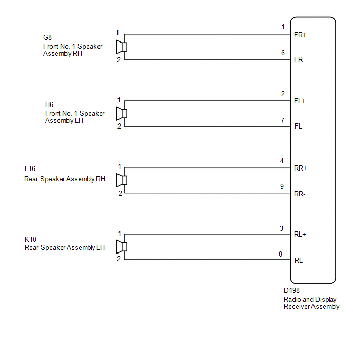
1. for 4 Speakers
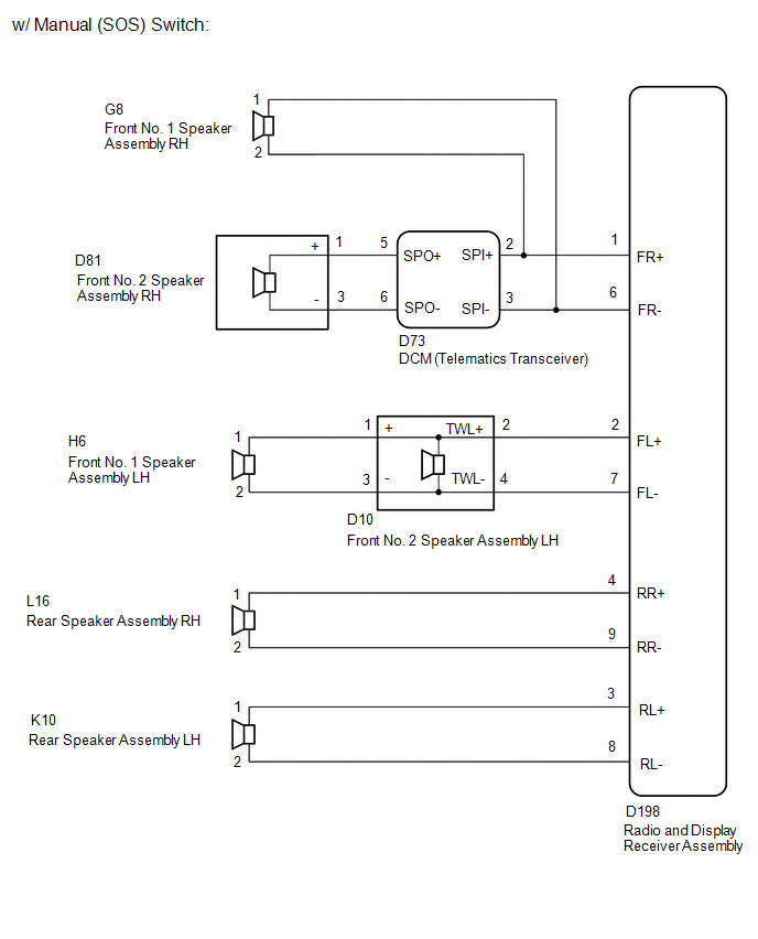
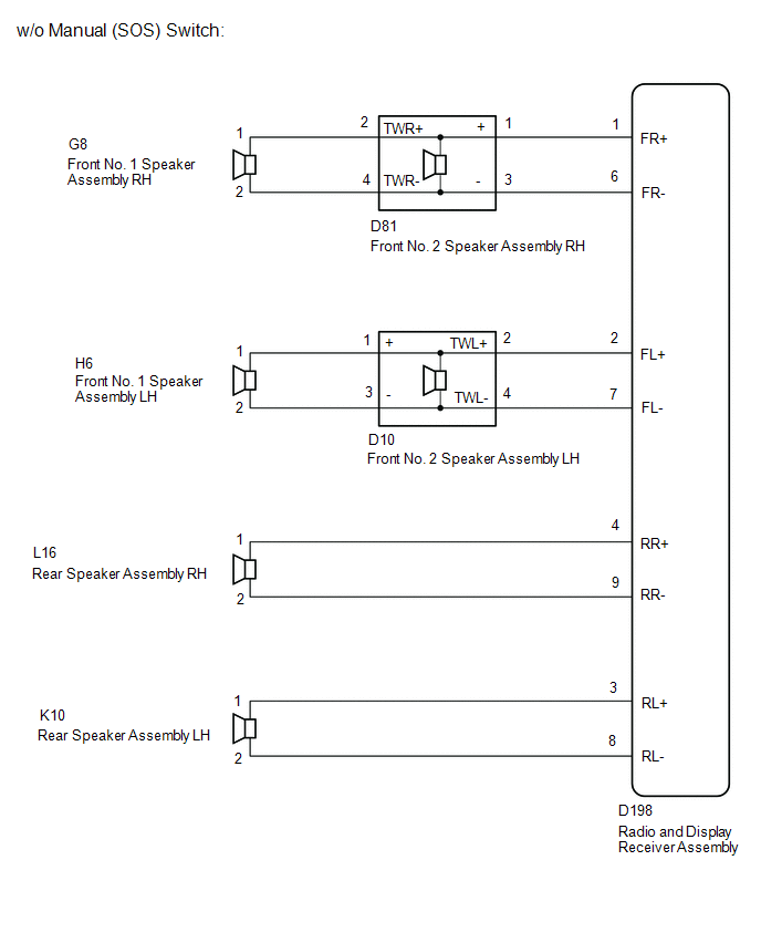
2. for 6 Speaker
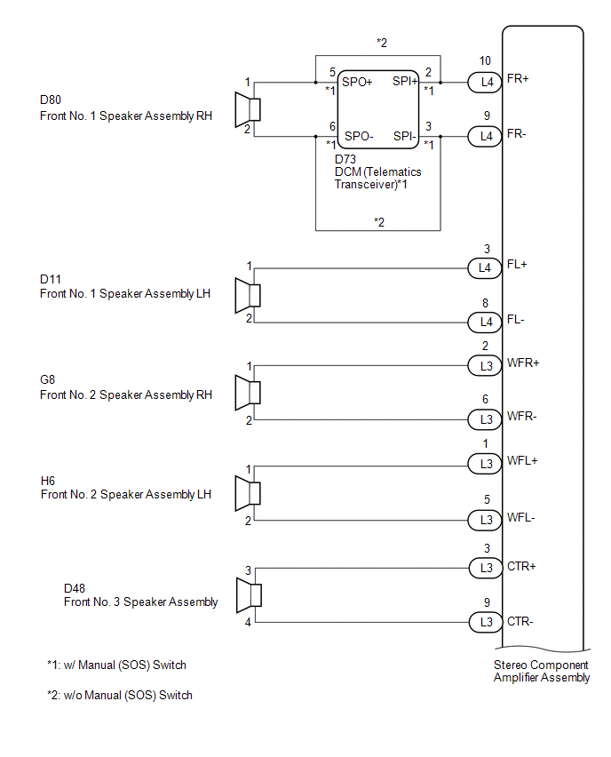
3. for 10 Speaker
CAUTION / NOTICE / HINT
NOTICE:
-
When replacing the radio and display receiver assembly, always replace it with a new one. If a radio and display receiver assembly which was installed to another vehicle is used, the following may occurs:
- A communication malfunction DTC may be stored.
- The radio and display receiver assembly may not operate normally.
-
Before replacing the DCM (telematics transceiver), refer to Registration.
Click here
![2018 - 2020 MY Sienna [11/2017 - ]; CELLULAR COMMUNICATION: SAFETY CONNECT SYSTEM: DCM ACTIVATION](/t3Portal/stylegraphics/info.gif)
PROCEDURE
|
1. |
CHECK MODEL |
(a) Choose the model to be inspected.
|
Result |
Proceed to |
|---|---|
|
for 4 Speakers |
A |
|
for 6 Speakers (w/ Manual (SOS) Switch) |
B |
|
for 6 Speakers (w/o Manual (SOS) Switch) |
C |
|
for 10 Speakers (w/ Manual (SOS) Switch) |
D |
|
for 10 Speakers (w/o Manual (SOS) Switch) |
E |
| B |

|
| C |
|
| D |
|
| E |
|
|

|
2. |
CHECK HARNESS AND CONNECTOR (SPEAKER CIRCUIT) |
(a) Disconnect the D198 radio and display receiver assembly connector.
(b) Disconnect the G8 and H6 front No. 1 speaker assembly connector.
(c) Disconnect the L16 and K10 rear speaker assembly connector.
(d) Measure the resistance according to the value(s) in the table below.
Standard Resistance:
|
Tester Connection |
Condition |
Specified Condition |
|---|---|---|
|
D198-1 (FR+) - Body ground |
Always |
10 kΩ or higher |
|
D198-6 (FR-) - Body ground |
Always |
10 kΩ or higher |
|
D198-2 (FL+) - Body ground |
Always |
10 kΩ or higher |
|
D198-7 (FL-) - Body ground |
Always |
10 kΩ or higher |
|
D198-4 (RR+) - Body ground |
Always |
10 kΩ or higher |
|
D198-9 (RR-) - Body ground |
Always |
10 kΩ or higher |
|
D198-3 (RL+) - Body ground |
Always |
10 kΩ or higher |
|
D198-8 (RL-) - Body ground |
Always |
10 kΩ or higher |
| NG |
|
REPAIR OR REPLACE HARNESS OR CONNECTOR |
|
|
3. |
INSPECT FRONT NO. 1 SPEAKER ASSEMBLY |
(a) Remove the front No. 1 speaker assembly.
Click here
(b) Inspect the front No. 1 speaker assembly.
Click here
| NG |
|
|
|
4. |
INSPECT REAR SPEAKER ASSEMBLY |
(a) Remove the rear speaker assembly.
Click here
(b) Inspect the rear speaker assembly.
Click here
| OK |
|
| NG |
|
|
5. |
CHECK HARNESS AND CONNECTOR (RADIO AND DISPLAY RECEIVER ASSEMBLY - BODY GROUND) |
(a) Disconnect the D198 radio and display receiver assembly connectors.
(b) Disconnect the G8 front No. 1 speaker assembly RH connector.
(c) Disconnect the D73 DCM (telematics transceiver) connector.
(d) Disconnect the D10 front No. 2 speaker assembly LH connector.
(e) Disconnect the L16 and K10 rear speaker assembly connectors.
(f) Measure the resistance between the radio and display receiver assembly and body ground to check for a short circuit in the wire harness.
Standard Resistance:
|
Tester Connection |
Condition |
Specified Condition |
|---|---|---|
|
D198-1 (FR+) - Body ground |
Always |
10 kΩ or higher |
|
D198-6 (FR-) - Body ground |
Always |
10 kΩ or higher |
|
D198-2 (FL+) - Body ground |
Always |
10 kΩ or higher |
|
D198-7 (FL-) - Body ground |
Always |
10 kΩ or higher |
|
D198-4 (RR+) - Body ground |
Always |
10 kΩ or higher |
|
D198-9 (RR-) - Body ground |
Always |
10 kΩ or higher |
|
D198-3 (RL+) - Body ground |
Always |
10 kΩ or higher |
|
D198-8 (RL-) - Body ground |
Always |
10 kΩ or higher |
| NG |
|
REPAIR OR REPLACE HARNESS OR CONNECTOR |
|
|
6. |
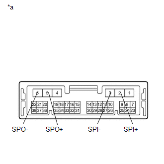
CHECK HARNESS AND CONNECTOR (DCM (TELEMATICS TRANSCEIVER) - BODY GROUND) |
(a) Disconnect the D73 DCM (telematics transceiver) connector.
(b) Disconnect the D81 front No. 2 speaker assembly RH connector.
(c) Measure the resistance between the DCM (telematics transceiver) and body ground to check for a short circuit in the wire harness.
Standard Resistance:
|
Tester Connection |
Condition |
Specified Condition |
|---|---|---|
|
D73-5 (SPO+) - Body ground |
Always |
10 kΩ or higher |
|
D73-6 (SPO-) - Body ground |
Always |
10 kΩ or higher |
| NG |
|
REPAIR OR REPLACE HARNESS OR CONNECTOR |
|
|
7. |
CHECK HARNESS AND CONNECTOR (FRONT NO. 2 SPEAKER ASSEMBLY LH - BODY GROUND) |
(a) Disconnect the H6 front No. 1 speaker assembly LH connector.
(b) Disconnect the D10 front No. 2 speaker assembly LH connector.
(c) Measure the resistance between the front No. 1 speaker assembly and body ground to check for a short circuit in the wire harness.
Standard Resistance:
|
Tester Connection |
Condition |
Specified Condition |
|---|---|---|
|
D10-1 (+) - Body ground |
Always |
10 kΩ or higher |
|
D10-3 (-) - Body ground |
Always |
10 kΩ or higher |
| NG |
|
|
|
8. |
INSPECT DCM (TELEMATICS TRANSCEIVER) |
(a) Remove the DCM (telematics transceiver).
Click here
|
(b) Measure the resistance according to the value(s) in the table below. Standard Resistance:
|
|

| OK |
|
| NG |
|
|
9. |
CHECK HARNESS AND CONNECTOR (RADIO AND DISPLAY RECEIVER ASSEMBLY - BODY GROUND) |
(a) Disconnect the D198 radio and display receiver assembly connectors.
(b) Disconnect the D81 and D10 front No. 2 speaker assembly connectors.
(c) Disconnect the L16 and K10 rear speaker assembly connectors.
(d) Measure the resistance between the radio and display receiver assembly and body ground to check for a short circuit in the wire harness.
Standard Resistance:
|
Tester Connection |
Condition |
Specified Condition |
|---|---|---|
|
D198-1 (FR+) - Body ground |
Always |
10 kΩ or higher |
|
D198-6 (FR-) - Body ground |
Always |
10 kΩ or higher |
|
D198-2 (FL+) - Body ground |
Always |
10 kΩ or higher |
|
D198-7 (FL-) - Body ground |
Always |
10 kΩ or higher |
|
D198-4 (RR+) - Body ground |
Always |
10 kΩ or higher |
|
D198-9 (RR-) - Body ground |
Always |
10 kΩ or higher |
|
D198-3 (RL+) - Body ground |
Always |
10 kΩ or higher |
|
D198-8 (RL-) - Body ground |
Always |
10 kΩ or higher |
| NG |
|
REPAIR OR REPLACE HARNESS OR CONNECTOR |
|
|
10. |
CHECK HARNESS AND CONNECTOR (FRONT NO. 2 SPEAKER ASSEMBLY - BODY GROUND) |
(a) Disconnect the G8 and H6 front No. 1 speaker assembly connectors.
(b) Disconnect the D81 and D10 front No. 2 speaker assembly connectors.
(c) Measure the resistance between each of the front No. 1 speaker assemblies and body ground to check for a short circuit in the wire harness.
Standard Resistance:
|
Tester Connection |
Condition |
Specified Condition |
|---|---|---|
|
D81-2 (TWR+) - Body ground |
Always |
10 kΩ or higher |
|
D81-4 (TWR-) - Body ground |
Always |
10 kΩ or higher |
|
D10-1 (+) - Body ground |
Always |
10 kΩ or higher |
|
D10-3 (-) - Body ground |
Always |
10 kΩ or higher |
| NG |
|
REPAIR OR REPLACE HARNESS OR CONNECTOR |
|
|
11. |
INSPECT FRONT NO. 1 SPEAKER ASSEMBLY |
(a) Remove the front No. 1 speaker assembly.
Click here
(b) Inspect the front No. 1 speaker assembly.
Click here
| NG |
|
|
|
12. |
INSPECT FRONT NO. 2 SPEAKER ASSEMBLY |
(a) Remove the front No. 2 speaker assembly.
Click here
(b) Inspect the front No. 2 speaker assembly.
Click here
| NG |
|
|
|
13. |
INSPECT REAR SPEAKER ASSEMBLY |
(a) Remove the rear speaker assembly.
Click here
(b) Inspect the rear speaker assembly.
Click here
| OK |
|
| NG |
|
|
14. |
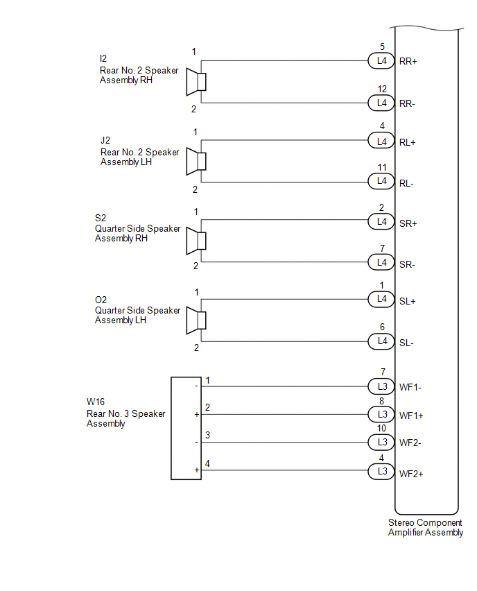
CHECK HARNESS AND CONNECTOR (STEREO COMPONENT AMPLIFIER ASSEMBLY - BODY GROUND) |
(a) Disconnect the L3 and L4 stereo component amplifier assembly connectors.
(b) Disconnect the D73 DCM (telematics transceiver) connector.
(c) Disconnect the G8 and H6 front No. 2 speaker assembly connectors.
(d) Disconnect the D11 front No. 1 speaker assembly LH connector.
(e) Disconnect the D48 front No. 3 speaker assembly connector.
(f) Disconnect the I2 and J2 rear No. 2 speaker assembly connectors.
(g) Disconnect the O2 and S2 quarter side speaker assembly connectors.
(h) Disconnect the W16 rear No. 3 speaker assembly connector.
(i) Measure the resistance between the stereo component amplifier assembly and body ground to check for a short circuit in the wire harness.
Standard Resistance:
|
Tester Connection |
Condition |
Specified Condition |
|---|---|---|
|
L4-10 (FR+) - Body ground |
Always |
10 kΩ or higher |
|
L4-9 (FR-) - Body ground |
Always |
10 kΩ or higher |
|
L4-3 (FL+) - Body ground |
Always |
10 kΩ or higher |
|
L4-8 (FL-) - Body ground |
Always |
10 kΩ or higher |
|
L4-5 (RR+) - Body ground |
Always |
10 kΩ or higher |
|
L4-12 (RR-) - Body ground |
Always |
10 kΩ or higher |
|
L4-4 (RL+) - Body ground |
Always |
10 kΩ or higher |
|
L4-11 (RL-) - Body ground |
Always |
10 kΩ or higher |
|
L4-2 (SR+) - Body ground |
Always |
10 kΩ or higher |
|
L4-7 (SR-) - Body ground |
Always |
10 kΩ or higher |
|
L4-1 (SL+) - Body ground |
Always |
10 kΩ or higher |
|
L4-6 (SL-) - Body ground |
Always |
10 kΩ or higher |
|
L3-3 (CTR+) - Body ground |
Always |
10 kΩ or higher |
|
L3-9 (CTR+) - Body ground |
Always |
10 kΩ or higher |
|
L3-2 (WFR+) - Body ground |
Always |
10 kΩ or higher |
|
L3-6 (WFR-) - Body ground |
Always |
10 kΩ or higher |
|
L3-1 (WFL+) - Body ground |
Always |
10 kΩ or higher |
|
L3-5 (WFL-) - Body ground |
Always |
10 kΩ or higher |
|
L3-8 (WF1+) - Body ground |
Always |
10 kΩ or higher |
|
L3-7 (WF1-) - Body ground |
Always |
10 kΩ or higher |
|
L3-4 (WF2+) - Body ground |
Always |
10 kΩ or higher |
|
L3-10 (WF2-) - Body ground |
Always |
10 kΩ or higher |
| NG |
|
REPAIR OR REPLACE HARNESS OR CONNECTOR |
|
|
15. |
CHECK HARNESS AND CONNECTOR (DCM (TELEMATICS TRANSCEIVER) - BODY GROUND) |
(a) Disconnect the D73 DCM (telematics transceiver) connector.
(b) Disconnect the D80 front No. 1 speaker assembly RH connector.
(c) Measure the resistance between the DCM (telematics transceiver) and body ground to check for a short circuit in the wire harness.
Standard Resistance:
|
Tester Connection |
Condition |
Specified Condition |
|---|---|---|
|
D73-5 (SPO+) - Body ground |
Always |
10 kΩ or higher |
|
D73-6 (SPO-) - Body ground |
Always |
10 kΩ or higher |
| NG |
|
REPAIR OR REPLACE HARNESS OR CONNECTOR |
|
|
16. |
INSPECT DCM (TELEMATICS TRANSCEIVER) |
(a) Remove the DCM (telematics transceiver)
Click here
|
(b) Measure the resistance according to the value(s) in the table below. Standard Resistance:
|
|
| OK |
|
| NG |
|
|
17. |
CHECK HARNESS AND CONNECTOR (STEREO COMPONENT AMPLIFIER ASSEMBLY - BODY GROUND) |
(a) Disconnect the L3 and L4 stereo component amplifier assembly connectors.
(b) Disconnect the G8 and H6 front No. 2 speaker assembly connectors.
(c) Disconnect the D11 and D80 front No. 1 speaker assembly connectors.
(d) Disconnect the D48 front No. 3 speaker assembly connector.
(e) Disconnect the I2 and J2 rear No. 2 speaker assembly connectors.
(f) Disconnect the O2 and S2 quarter side speaker assembly connectors.
(g) Disconnect the W16 rear No. 3 speaker assembly connector.
(h) Measure the resistance between the stereo component amplifier assembly and body ground to check for a short circuit in the wire harness.
Standard Resistance:
|
Tester Connection |
Condition |
Specified Condition |
|---|---|---|
|
L4-10 (FR+) - Body ground |
Always |
10 kΩ or higher |
|
L4-9 (FR-) - Body ground |
Always |
10 kΩ or higher |
|
L4-3 (FL+) - Body ground |
Always |
10 kΩ or higher |
|
L4-8 (FL-) - Body ground |
Always |
10 kΩ or higher |
|
L4-5 (RR+) - Body ground |
Always |
10 kΩ or higher |
|
L4-12 (RR-) - Body ground |
Always |
10 kΩ or higher |
|
L4-4 (RL+) - Body ground |
Always |
10 kΩ or higher |
|
L4-11 (RL-) - Body ground |
Always |
10 kΩ or higher |
|
L4-2 (SR+) - Body ground |
Always |
10 kΩ or higher |
|
L4-7 (SR-) - Body ground |
Always |
10 kΩ or higher |
|
L4-1 (SL+) - Body ground |
Always |
10 kΩ or higher |
|
L4-6 (SL-) - Body ground |
Always |
10 kΩ or higher |
|
L3-3 (CTR+) - Body ground |
Always |
10 kΩ or higher |
|
L3-9 (CTR+) - Body ground |
Always |
10 kΩ or higher |
|
L3-2 (WFR+) - Body ground |
Always |
10 kΩ or higher |
|
L3-6 (WFR-) - Body ground |
Always |
10 kΩ or higher |
|
L3-1 (WFL+) - Body ground |
Always |
10 kΩ or higher |
|
L3-5 (WFL-) - Body ground |
Always |
10 kΩ or higher |
|
L3-8 (WF1+) - Body ground |
Always |
10 kΩ or higher |
|
L3-7 (WF1-) - Body ground |
Always |
10 kΩ or higher |
|
L3-4 (WF2+) - Body ground |
Always |
10 kΩ or higher |
|
L3-10 (WF2-) - Body ground |
Always |
10 kΩ or higher |
| NG |
|
REPAIR OR REPLACE HARNESS OR CONNECTOR |
|
|
18. |
INSPECT FRONT NO. 1 SPEAKER ASSEMBLY |
(a) Remove the front No. 1 speaker assembly.
Click here
(b) Inspect the front No. 1 speaker assembly.
Click here
| NG |
|
|
|
19. |
INSPECT FRONT NO. 2 SPEAKER ASSEMBLY |
(a) Remove the front No. 2 speaker assembly.
Click here
(b) Inspect the front No. 2 speaker assembly.
Click here
| NG |
|
|
|
20. |
INSPECT FRONT NO. 3 SPEAKER ASSEMBLY |
(a) Remove the front No. 3 speaker assembly.
Click here
(b) Inspect the front No. 3 speaker assembly.
Click here
| NG |
|
|
|
21. |
INSPECT REAR NO. 2 SPEAKER ASSEMBLY |
(a) Remove the rear No. 2 speaker assembly.
Click here
(b) Inspect the rear No. 2 speaker assembly.
Click here
| NG |
|
|
|
22. |
INSPECT QUARTER SIDE SPEAKER ASSEMBLY |
(a) Remove the quarter side speaker assembly.
Click here
(b) Inspect the quarter side speaker assembly.
Click here
| NG |
|
|
|
23. |
INSPECT REAR NO. 3 SPEAKER ASSEMBLY |
(a) Remove the rear No. 3 speaker assembly.
Click here
(b) Inspect the rear No. 3 speaker assembly.
Click here
| OK |
|
| NG |
|
|
|
|