| Last Modified: 08-28-2024 | 6.11:8.1.0 | Doc ID: RM10000000105GV |
| Model Year Start: 2017 | Model: Sienna | Prod Date Range: [08/2016 - ] |
| Title: UA80F (AUTOMATIC TRANSMISSION / TRANSAXLE): TRANSMISSION WIRE: REMOVAL; 2017 - 2020 MY Sienna [08/2016 - ] | ||
REMOVAL
PROCEDURE
1. PRECAUTION
NOTICE:
After turning the ignition switch off, waiting time may be required before disconnecting the cable from the negative (-) battery terminal. Therefore, make sure to read the disconnecting the cable from the negative (-) battery terminal notices before proceeding with work.
Click here
![2017 - 2020 MY Sienna [08/2016 - ]; INTRODUCTION: REPAIR INSTRUCTION: PRECAUTION](/t3Portal/stylegraphics/info.gif)
2. DISCONNECT CABLE FROM NEGATIVE BATTERY TERMINAL
NOTICE:
When disconnecting the cable, some systems need to be initialized after the cable is reconnected.
Click here
3. REMOVE FRONT WHEEL LH
4. REMOVE NO. 1 ENGINE UNDER COVER
Click here
5. REMOVE NO. 2 ENGINE UNDER COVER
Click here
6. REMOVE FRONT FENDER APRON SEAL LH
Click here
7. DRAIN AUTOMATIC TRANSAXLE FLUID
Click here
8. REMOVE WINDSHIELD WIPER MOTOR AND LINK
Click here
9. REMOVE OUTER COWL TOP PANEL SUB-ASSEMBLY
Click here
10. REMOVE V-BANK COVER SUB-ASSEMBLY
Click here
11. REMOVE BATTERY
Click here
12. REMOVE AIR CLEANER INLET ASSEMBLY
Click here
13. REMOVE AIR CLEANER CAP WITH AIR CLEANER HOSE
Click here
14. REMOVE AIR CLEANER FILTER ELEMENT SUB-ASSEMBLY
Click here
15. REMOVE AIR CLEANER CASE SUB-ASSEMBLY
Click here
16. REMOVE AIR CLEANER BRACKET
Click here
17. REMOVE DUTY VACUUM SWITCHING VALVE
Click here
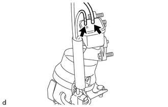
18. REMOVE VACUUM SURGE TANK WITH BRACKET
|
(a) Disconnect the 2 vacuum hose sub-assembly from the vacuum surge tank. |
|
|
(b) Remove the 2 bolts and vacuum surge tank with bracket from the front engine mounting bracket. |
|
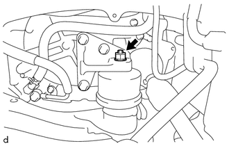
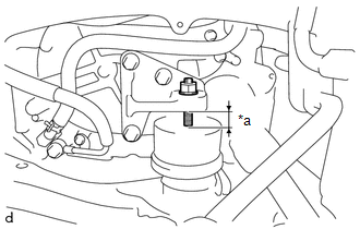
19. REMOVE TRANSMISSION OIL THERMOSTAT
Click here
20. REMOVE FRONT SUSPENSION MEMBER DYNAMIC DAMPER
Click here
21. REMOVE THROTTLE BODY WITH MOTOR ASSEMBLY
Click here
22. DISCONNECT VENTILATION HOSE
Click here
23. DISCONNECT PURGE VALVE (PURGE VSV)
Click here
24. REMOVE NO. 2 SURGE TANK STAY
Click here
25. REMOVE INTAKE AIR SURGE TANK ASSEMBLY
Click here
26. REMOVE AIR SURGE TANK TO INTAKE MANIFOLD GASKET
Click here
27. REMOVE WIRE HARNESS CLAMP BRACKET
|
(a) Disconnect the air fuel ratio sensor (for Bank 1) connector. |
|
|
(b) Disengage the hose clamp and 3 wire harness clamps. |
|
(c) Remove the bolt and wire harness clamp bracket from the cylinder head RH.
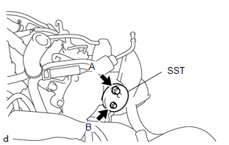
28. INSTALL ENGINE HANGER
|
(a) Install the SST (engine hanger attachment) to the cylinder head RH. SST: 09940-30010 91671-10825 Torque: Bolt (A) : 33 N·m {337 kgf·cm, 24 ft·lbf} Bolt (B) : 10 N·m {102 kgf·cm, 7 ft·lbf}
NOTICE: Do not use any bolts other than the specified bolt. |
|
|
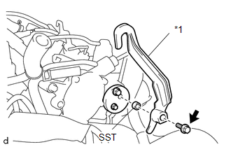
(b) Install the SST (collar) and No. 1 engine hanger to the engine hanger attachment with the bolt. Torque: 43 N·m {438 kgf·cm, 32 ft·lbf}
|
|
|
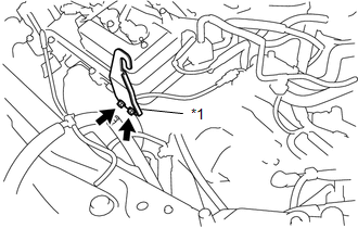
(c) Install the No. 2 engine hanger to the cylinder head LH with the 2 bolts. Torque: 33 N·m {337 kgf·cm, 24 ft·lbf}
|
|
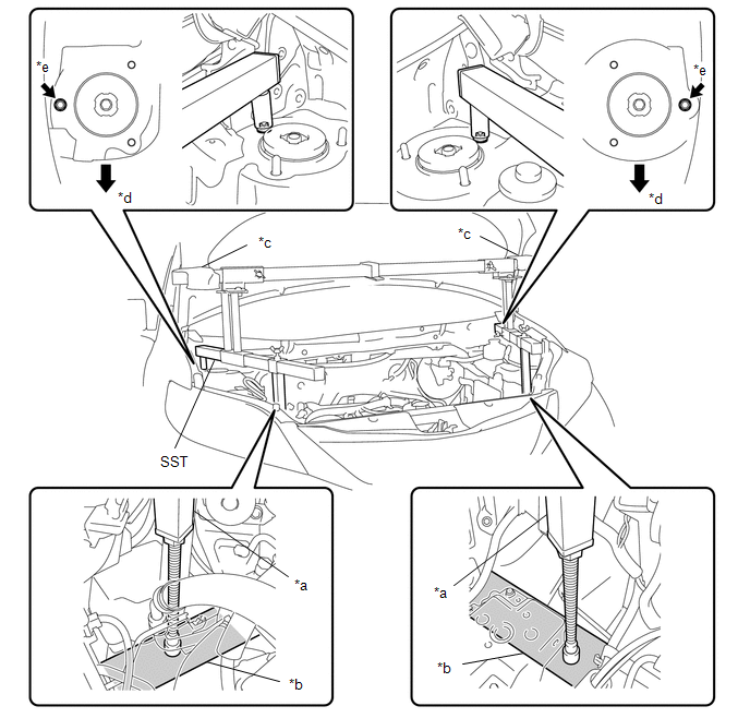
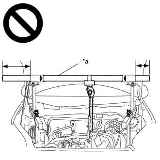
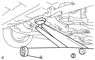
29. INSTALL ENGINE SUPPORT BRIDGE
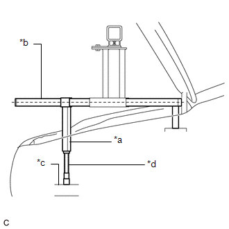
(a) Install SST to the vehicle body as shown in the illustration.
|
*a |
Support Shaft |
*b |
Front Side Member |
|
*c |
Cloth |
*d |
Front Side |
|
*e |
Front Suspension Nut |
- |
- |
SST: 09940-10020
CAUTION:
-
Make sure that no oil or grease is on the front side member, and set the support shaft on the level surface of the front side member.
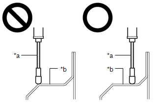
*a
Support Shaft
*b
Front Side Member
- The engine support bridge may fall off if any oil or grease is still on or it is installed on the unlevel surface.
NOTICE:
- Prevent SST from contacting the vehicle body exterior and windshield glass.
- To prevent damage to the engine hood, place pieces of cloth between the engine hood and SST.
- Lightly shake SST by hand to make sure it is securely installed before performing work.
|
(b) Turn the threaded portion of each support shaft to adjust its height until the sub beams are parallel to the ground. |
|
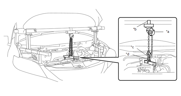
(c) Install the chain block to the sling bracket.
|
*a |
Chain Block |
*b |
Sling Bracket |
|
*c |
Fuse Shackle |
*d |
Shackle (A) |
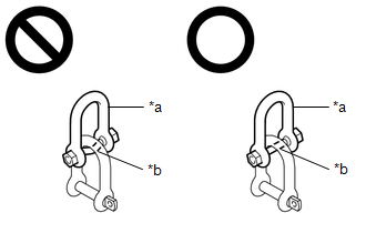
(d) Install the division bar to the chain block with the shackles.
CAUTION:
-
Make sure the fuse shackle is on the chain block side and the shackle (A) is on the division bar side as shown in the illustration so that the fuse bolt is visible and can be checked for deformation easily.
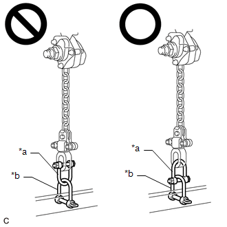
*a
Fuse Shackle
*b
Shackle (A)
- If the fuse shackle is installed upside down, deformation of the fuse bolt will not be visible and cannot be used to tell if the load capacity of the engine support bridge has been exceeded. If the load capacity is exceeded, it may cause the engine support bridge to damage the vehicle and the engine assembly with automatic transaxle assembly may fall.
-
Make sure that the fuse bolt of the fuse shackle is free of damage, such as deformation or cracks. If damaged, replace the fuse shackle.
*a
Fuse Shackle
*b
Fuse Bolt
- If a deformed fuse bolt is used, it cannot be used to tell if the load capacity of the engine support bridge has been exceeded. If the load capacity is exceeded, it may cause the engine support bridge to damage the vehicle and the engine assembly with transaxle assembly may fall.
(e) Connect the division bar to the No. 1 engine hanger with the 2 shackles (A).
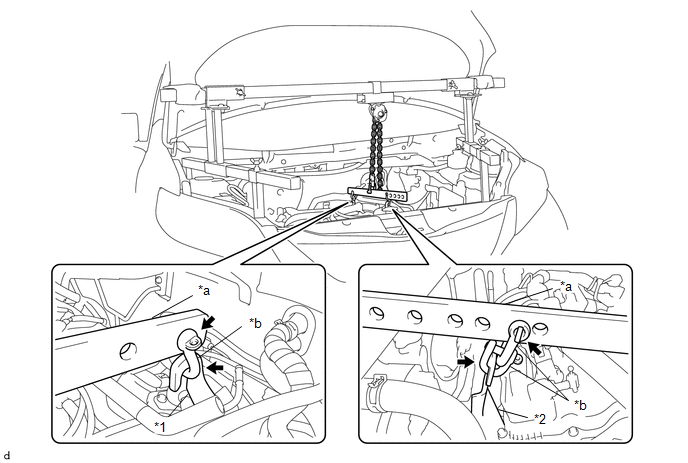
|
*1 |
No. 1 Engine Hanger |
*2 |
No. 2 Engine Hanger |
|
*a |
Division Bar |
*b |
Shackle (A) |
(f) Connect the division bar to the No. 2 engine hanger with the shackle (A).
(g) Make sure the distance between the chain block assembly and suspension ring is 120 mm (4.72 in.) or more.
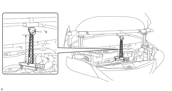
|
*a |
Chain Block Assembly |
*b |
Division Bar |
|
*c |
120 mm (4.72 in.) or more |
- |
- |
HINT:
If the suspension height is less than 120 mm, adjust the links of the chain which connect the division bar and engine hanger.
(h) Adjust the position of the chain block assembly so that the chain is perpendicular to the SST main beam and sub beams as shown in the illustration.
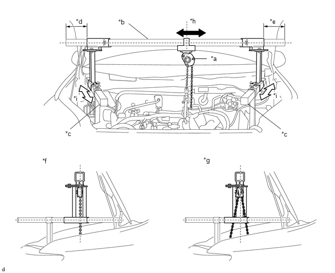
|
*a |
Chain Block Assembly |
*b |
Main Beam |
|
*c |
Sub Beam |
*d |
Dimension (A) |
|
*e |
Dimension (B) |
*f |
Correct |
|
*g |
Incorrect |
*h |
Right to Left Adjustment |
|
*i |
Front to Rear Adjustment |
- |
- |
CAUTION:
- To prevent the engine with automatic transaxle assembly from falling, make sure that the length of dimension (A) and dimension (B) are equal.
-
Do not perform any procedures if the length of dimension (A) and dimension (B) are not equal.
*a
Main Beam
- Performing any procedure when the length of dimension (A) and dimension (B) are not equal may cause the engine assembly with automatic transaxle assembly and engine support bridge to fall, possibly causing serious injury.
(i) Confirm the appropriate installation state of the engine support bridge and tighten the 6 wing bolts and 2 bolts.

|
*a |
Wing Bolt |
*b |
Bolt |
Torque:
Bolt :
30 N·m {306 kgf·cm, 22 ft·lbf}
CAUTION:
-
Do not perform any procedures before tightening the bolts to the specified torque.
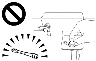
- Performing procedures without tightening the bolts to the specified torque, may cause the engine support bridge to fall.
(j) Tighten the chain block assembly until it cannot be moved any further by hand.
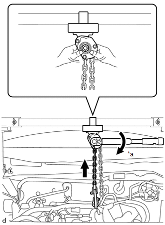
|
*a |
Turn |
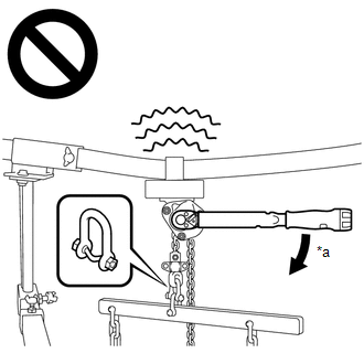
|
*a |
41 N*m (418 kgf*cm, 30 ft.*lbf) or more |
- When suspending the engine with automatic transaxle assembly, do not tighten the chain block assembly more than 41 N*m (418 kgf*cm, 30 ft.*lbf).
- Tightening the chain block assembly more than 41 N*m (418 kgf*cm, 30 ft.*lbf) will cause the load capacity (400 kg (881.8 lb)) to be exceeded and may cause damage to the engine support bridge and vehicle body.
30. SUPPORT AUTOMATIC TRANSAXLE ASSEMBLY
|
(a) Support the automatic transaxle assembly with a jack. Insert a wooden block between the jack and the automatic transaxle assembly to prevent damage. |
|
31. DISCONNECT NO. 2 OUTLET OIL COOLER HOSE
Click here
32. DISCONNECT NO. 1 TRANSMISSION OIL COOLER HOSE
Click here
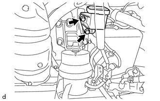
33. REMOVE OIL COOLER UNION SUB-ASSEMBLY
|
(a) Remove the bolt to separate the oil cooler union sub-assembly from the automatic transaxle case sub-assembly. |
|
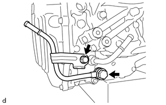
(b) Remove the oil cooler union bolt, 2 gaskets and oil cooler union sub-assembly from the automatic transaxle case sub-assembly.
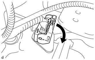
34. REMOVE TRANSMISSION CASE SIDE COVER
|
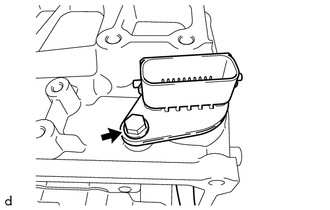
(a) Disconnect the transmission wire connector. HINT: Disengage the claw, pull down the lever, and then disconnect the transmission wire connector. |
|
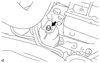
|
(b) Loosen the bolt from the engine mounting insulator. NOTICE: Do not fully remove the bolt. |
|
|
(c) Loosen the nut from the engine mounting insulator LH. NOTICE: Do not fully remove the nut. |
|
|
(d) Operate the engine support bridge and the jack to raise up the engine and automatic transaxle assembly from 25 to 30 mm (0.984 to 1.181 in.). NOTICE:
|
|
|
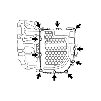
(e) Remove the 10 bolts and transmission case side cover from the automatic transaxle case sub-assembly. |
|
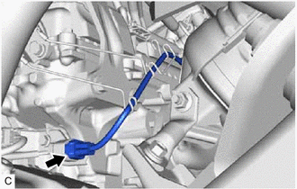
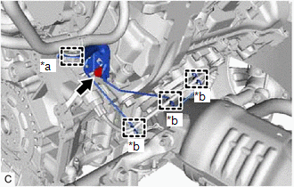
35. REMOVE TRANSMISSION WIRE
|
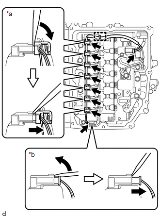
(a) Disengage the clamp, and disconnect the 9 shift solenoid valve connectors. HINT:
|
|
|
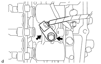
(b) Remove the bolt and temperature sensor clamp and disconnect the temperature sensor from the transmission valve body assembly. |
|
|
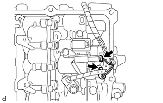
(c) Disconnect the transmission revolution sensor (NT) connector and transmission revolution sensor (NC) connector. |
|
|
(d) Remove the bolt and transmission wire from the automatic transmission case sub-assembly. |
|
|
|
|