- Compressor and magnetic clutch (A/C lock sensor)
- Compressor drive belt
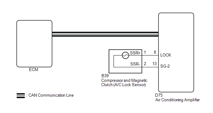
- Harness or connector between compressor and magnetic clutch and air conditioning amplifier
- Air conditioning amplifier
- CAN communication system
| Last Modified: 08-28-2024 | 6.11:8.1.0 | Doc ID: RM100000000ZXIB |
| Model Year Start: 2017 | Model: Sienna | Prod Date Range: [08/2016 - ] |
| Title: HEATING / AIR CONDITIONING: AIR CONDITIONING SYSTEM: B1422/22; Compressor Lock Sensor Circuit; 2017 - 2020 MY Sienna [08/2016 - ] | ||
|
DTC |
B1422/22 |
Compressor Lock Sensor Circuit |
SYSTEM DESCRIPTION
The ECM sends the engine speed signal to the air conditioning amplifier via CAN communication.
The air conditioning amplifier reads the difference between compressor speed and engine speed. When the difference becomes too large, the air conditioning amplifier determines that the compressor is locked, and turns the magnetic clutch off.
|
DTC Code |
DTC Detection Condition |
Trouble Area |
|---|---|---|
|
B1422/22 |
Open or short in compressor lock sensor circuit |
|
WIRING DIAGRAM
PROCEDURE
|
1. |
CHECK COMPRESSOR AND MAGNETIC CLUTCH |
(a) Use the Techstream to check if the CAN communication system is functioning normally.
Result
|
Result |
Proceed to |
|---|---|
|
CAN DTC is not output |
A |
|
CAN DTC is output |
B |
| B |

|
GO TO CAN COMMUNICATION SYSTEM (See page
|
![2017 MY Sienna [08/2016 - 11/2017]; NETWORKING: CAN COMMUNICATION SYSTEM: HOW TO PROCEED WITH TROUBLESHOOTING](/t3Portal/stylegraphics/info.gif)
|

|
2. |
INSPECT COMPRESSOR AND MAGNETIC CLUTCH (A/C LOCK SENSOR) |
|
(a) Disconnect the Compressor and magnetic clutch connector. |
|
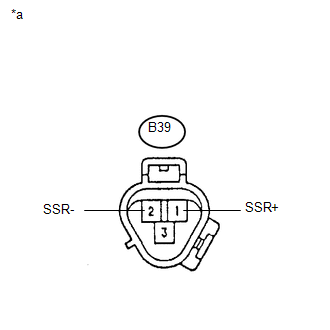
(b) Measure the resistance according to the value(s) in the table below.
Standard Resistance:
|
Tester Connection |
Condition |
Specified Condition |
|---|---|---|
|
B39-1 (SSR+) - B39-2 (SSR-) |
20°C (68°F) |
160 to 320 Ω |
| NG |
|
|
|
3. |
CHECK HARNESS AND CONNECTOR (AIR CONDITIONING AMPLIFIER - A/C LOCK SENSOR) |
(a) Disconnect the D75 air conditioning amplifier connector.
(b) Measure the resistance according to the value(s) in the table below.
Standard Resistance:
|
Tester Connection |
Condition |
Specified Condition |
|---|---|---|
|
D75-8 (LOCK) - B39-1 (SSR+) |
Always |
Below 1 Ω |
|
D75-13 (SG-2) - B39-2 (SSR-) |
Always |
Below 1 Ω |
|
D75-8 (LOCK) - Body ground |
Always |
10 kΩ or higher |
|
D75-13 (SG-2) - Body ground |
Always |
10 kΩ or higher |
Result
|
Result |
Proceed to |
|---|---|
|
NG |
A |
|
OK (When troubleshooting according to Problem Symptoms Table) |
B |
|
OK (When troubleshooting according to the DTC) |
C |
| A |
|
REPAIR OR REPLACE HARNESS OR CONNECTOR |
| B |
|
PROCEED TO NEXT SUSPECTED AREA SHOWN IN PROBLEM SYMPTOMS TABLE |
| C |
|
|
|
|