| Last Modified: 08-28-2024 | 6.11:8.1.0 | Doc ID: RM100000000ZX9V |
| Model Year Start: 2017 | Model: Sienna | Prod Date Range: [08/2016 - 11/2017] |
| Title: CRUISE CONTROL: DYNAMIC RADAR CRUISE CONTROL SYSTEM: TC and CG Terminal Circuit; 2017 MY Sienna [08/2016 - 11/2017] | ||
|
TC and CG Terminal Circuit |
DESCRIPTION
Connecting terminals TC and CG of the DLC3 causes the system to enter the self-diagnostic mode. If a malfunction is present, the MIL will blink.
HINT:
When a particular warning light remains blinking, a ground short in the wiring of terminal TC of the DLC3 or an internal ground short in the relevant ECU is suspected.
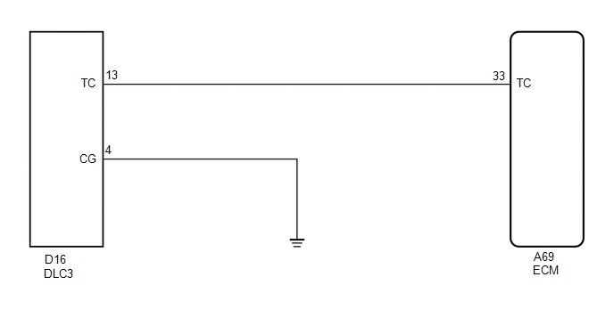
WIRING DIAGRAM
PROCEDURE
|
1. |
CHECK HARNESS AND CONNECTOR (TERMINAL TC of DLC3 - ECM) |
|
(a) Disconnect the ECM connector. |
|
(b) Measure the resistance according to the value(s) in the table below.
Standard Resistance:
|
Tester Connection |
Condition |
Specified Condition |
|---|---|---|
|
A69-33 (TC) - D16-13 (TC) |
Always |
Below 1 Ω |
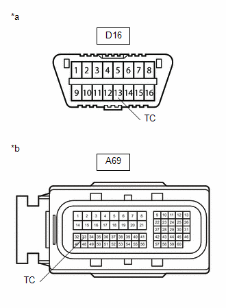
Text in Illustration
|
*a |
DLC3 |
|
*b |
Front view of wire harness connector (to ECM) |
| NG |

|
REPAIR OR REPLACE HARNESS OR CONNECTOR |
|

|
2. |
CHECK HARNESS AND CONNECTOR (TERMINAL CG of DLC3 - BODY GROUND) |
(a) Measure the resistance according to the value(s) in the table below.
Standard Resistance:
|
Tester Connection |
Condition |
Specified Condition |
|---|---|---|
|
D16-4 (CG) - Body ground |
Always |
Below 1 Ω |
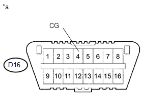
Text in Illustration
|
*a |
DLC3 |
| NG |
|
REPAIR OR REPLACE HARNESS OR CONNECTOR |
|
|
3. |
CHECK HARNESS AND CONNECTOR (TERMINAL TC of DLC3 - BODY GROUND) |
(a) Measure the resistance according to the value(s) in the table below.
Standard Resistance:
|
Tester Connection |
Condition |
Specified Condition |
|---|---|---|
|
D16-13 (TC) - Body ground |
Always |
10 kΩ or higher |
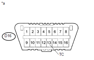
Text in Illustration
|
*a |
DLC3 |
| OK |
|
PROCEED TO NEXT SUSPECTED AREA SHOWN IN PROBLEM SYMPTOMS TABLE |
| NG |
|
REPAIR OR REPLACE HARNESS OR CONNECTOR OR EACH ECU |
|
|
|