| Last Modified: 08-28-2024 | 6.11:8.1.0 | Doc ID: RM100000000ZQO4 |
| Model Year Start: 2017 | Model: Sienna | Prod Date Range: [08/2016 - 11/2017] |
| Title: BRAKE CONTROL / DYNAMIC CONTROL SYSTEMS: VEHICLE STABILITY CONTROL SYSTEM: Brake Warning Light Remains ON; 2017 MY Sienna [08/2016 - 11/2017] | ||
|
Brake Warning Light Remains ON |
DESCRIPTION
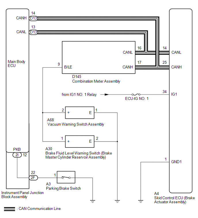
The skid control ECU is connected to the combination meter via CAN communication.
If any of the following is detected, the brake warning light remains on:
- The skid control ECU connector is disconnected from the skid control ECU.
- The brake fluid level is insufficient.
- The parking brake is applied.
- EBD operation has been disabled.
- The vacuum inside the brake booster decreases.
WIRING DIAGRAM
CAUTION / NOTICE / HINT
NOTICE:
When replacing the brake actuator assembly, perform zero point calibration and store system information (See page
![2016 - 2017 MY Sienna [12/2015 - 11/2017]; BRAKE CONTROL / DYNAMIC CONTROL SYSTEMS: VEHICLE STABILITY CONTROL SYSTEM: CALIBRATION](/t3Portal/stylegraphics/info.gif) ).
).
PROCEDURE
|
1. |
CHECK CAN COMMUNICATION SYSTEM |
(a) Check if a CAN communication system DTC is output (See page
).
Result
|
Result |
Proceed to |
|---|---|
|
DTC is not output |
A |
|
DTC is output |
B |
| B |

|
|

|
2. |
CHECK IF SKID CONTROL ECU CONNECTOR IS SECURELY CONNECTED |
(a) Check if the skid control ECU connector is securely connected.
OK:
The connector is securely connected.
| NG |
|
CONNECT CONNECTOR TO ECU CORRECTLY |
|
|
3. |
INSPECT BATTERY |
(a) Check the battery voltage.
Standard voltage:
11 to 14 V
| NG |
|
|
|
4. |
INSPECT SKID CONTROL ECU (IG1 TERMINAL) |
|
(a) Disconnect the skid control ECU connector. |
|
(b) Turn the ignition switch to ON.
(c) Measure the voltage according to the value(s) in the table below.
Standard Voltage:
|
Tester Connection |
Switch Condition |
Specified Condition |
|---|---|---|
|
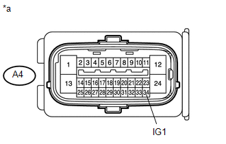
A4-34 (IG1) - Body ground |
Ignition switch ON |
11 to 14 V |
Text in Illustration
|
*a |
Front view of wire harness connector (to Skid Control ECU) |
| NG |
|
REPAIR OR REPLACE HARNESS OR CONNECTOR (IG1 CIRCUIT) |
|
|
5. |
INSPECT SKID CONTROL ECU (GND1 TERMINAL) |
|
(a) Turn the ignition switch off. |
|
(b) Measure the resistance according to the value(s) in the table below.
Standard Resistance:
|
Tester Connection |
Condition |
Specified Condition |
|---|---|---|
|
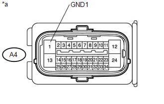
A4-1 (GND1) - Body ground |
Always |
Below 1 Ω |
Text in Illustration
|
*a |
Front view of wire harness connector (to Skid Control ECU) |
| NG |
|
REPAIR OR REPLACE HARNESS OR CONNECTOR (GND1 CIRCUIT) |
|
|
6. |
READ VALUE USING TECHSTREAM (PARKING BRAKE SWITCH) |
(a) Reconnect the skid control ECU connector.
(b) Connect the Techstream to the DLC3.
(c) Turn the ignition switch to ON.
(d) Turn the Techstream on.
(e) Enter the following menus: Chassis / ABS/VSC/ TRAC / Data List.
(f) Select the Data List on the Techstream (See page
).
ABS/VSC/TRAC
|
Tester Display |
Measurement Item/Range |
Normal Condition |
Diagnostic Note |
|---|---|---|---|
|
Parking Brake SW |
Parking brake switch / ON or OFF |
ON: Parking brake applied OFF: Parking brake released |
- |
(g) Using the Techstream, check the switch condition on the Techstream changes according to parking brake pedal operation.
OK:
The Techstream displays ON or OFF according to parking brake pedal operation.
| NG |
|
|
|
7. |
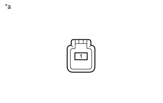
INSPECT BRAKE FLUID LEVEL WARNING SWITCH |
|
(a) Turn the ignition switch off. |
|
(b) Remove the reservoir filler cap and strainer.
(c) Disconnect the brake fluid level warning switch connector.
(d) Measure the resistance according to the value(s) in the table below.
HINT:
A float is located inside the reservoir. Its position can be changed by increasing or decreasing the level of brake fluid.
Standard Resistance:
|
Tester Connection |
Switch Condition |
Specified Condition |
|---|---|---|
|
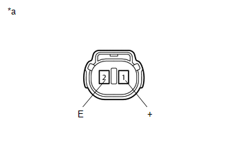
1 (+) - 2 (E) |
Brake fluid level warning switch OFF (Float up) |
1.9 to 2.1 kΩ |
|
1 (+) - 2 (E) |
Brake fluid level warning switch ON (Float down) |
Below 1 Ω |
HINT:
If there is no problem after finishing the above check, adjust the brake fluid level to the MAX level.
Text in Illustration
|
*a |
Component without harness connected (Brake Fluid Level Warning Switch) |
| NG |
|
REPLACE BRAKE MASTER CYLINDER RESERVOIR ASSEMBLY (BRAKE FLUID LEVEL WARNING SWITCH) |
|
|
8. |
INSPECT VACUUM WARNING SWITCH ASSEMBLY |
(a) Inspect the vacuum warning switch assembly.
Click here
OK:
The vacuum warning switch assembly is normal.
| NG |
|
|
|
9. |
CHECK HARNESS AND CONNECTOR (BRAKE WARNING LIGHT CIRCUIT) |
(a) Disconnect the combination meter connector.
(b) Measure the resistance according to the value(s) in the table below.
Standard Resistance:
|
Tester Connection |
Condition |
Specified Condition |
|---|---|---|
|
D145-9 (B/LE) - A30-1 (+) |
Always |
Below 1 Ω |
|
D145-9 (B/LE) - Body ground |
Always |
10 kΩ or higher |
|
A30-2 (E) - Body ground |
Always |
Below 1 Ω |
|
D145-9 (B/LE) - A68-2 (+) |
Always |
Below 1 Ω |
|
A68-1 (E) - Body ground |
Always |
Below 1 Ω |
| NG |
|
REPAIR OR REPLACE HARNESS OR CONNECTOR |
|
|
10. |
PERFORM ACTIVE TEST USING TECHSTREAM (BRAKE WARNING LIGHT) |
(a) Reconnect the skid control ECU connector.
(b) Connect the Techstream to the DLC3.
(c) Turn the ignition switch to ON.
(d) Turn the Techstream on.
(e) Enter the following menus: Body Electrical / Combination Meter / Active Test.
(f) Select the Active Test on the Techstream.
Combination Meter
|
Tester Display |
Test Part |
Control Range |
Diagnostic Note |
|---|---|---|---|
|
Indicat. Lamp Brake |
Brake warning light |
OFF or ON |
Operate with IG ON and the vehicle is stopped. |
(g) Check that the brake warning light on the combination meter turns on or off in accordance with the Techstream operation.
OK:
The brake warning light turns on or off in accordance with the Techstream operation.
HINT:
If troubleshooting has been carried out according to Problem Symptoms Table, refer back to the table and proceed to the next step before replacing the part (See page ).
Click here
| OK |
|
| NG |
|
|
11. |
INSPECT PARKING BRAKE SWITCH |
|
(a) Turn the ignition switch off. |
|
(b) Disconnect the parking brake switch connector.
(c) Measure the resistance according to the value(s) in the table below.
Standard Resistance:
|
Tester Connection |
Switch Condition |
Specified Condition |
|---|---|---|
|
1 - Body ground |
Parking brake switch ON (Switch pin free) |
Below 1 Ω |
|
1 - Body ground |
Parking brake switch OFF (Switch pin pushed in) |
10 kΩ or higher |
Text in Illustration
|
*a |
Component without harness connected (Parking Brake Switch) |
| NG |
|
|
|
12. |
CHECK HARNESS AND CONNECTOR (INSTRUMENT PANEL JUNCTION BLOCK - PARKING BRAKE SWITCH) |
(a) Disconnect the instrument panel junction block assembly connector.
(b) Measure the resistance according to the value(s) in the table below.
Standard Resistance:
|
Tester Connection |
Condition |
Specified Condition |
|---|---|---|
|
2F-22 - A3-1 |
Always |
Below 1 Ω |
|
2F-22 - Body ground |
Always |
10 kΩ or higher |
| NG |
|
REPAIR OR REPLACE HARNESS OR CONNECTOR |
|
|
13. |
CHECK HARNESS AND CONNECTOR (INSTRUMENT PANEL JUNCTION BLOCK - MAIN BODY ECU) |
(a) Remove the main body ECU from the instrument panel junction block assembly.
(b) Measure the resistance according to the value(s) in the table below.
Standard Resistance:
|
Tester Connection |
Condition |
Specified Condition |
|---|---|---|
|
2I-12 - 2F-22 |
Always |
Below 1 Ω |
|
2I-12 - Body ground |
Always |
10 kΩ or higher |
HINT:
If troubleshooting has been carried out according to Problem Symptoms Table, refer back to the table and proceed to the next step before replacing the part (See page
).
| OK |
|
| NG |
|
REPLACE INSTRUMENT PANEL JUNCTION BLOCK ASSEMBLY |
|
|
|