- Engine coolant temperature: 65°C (149°F) or lower (3 PTC heater relays operating)
- Engine coolant temperature: 70°C (158°F) or lower (2 PTC heater relays operating)
- Engine coolant temperature: 75°C (167°F) or lower (1 PTC heater relay operating)
| Last Modified: 08-28-2024 | 6.11:8.1.0 | Doc ID: RM100000000ZPDG |
| Model Year Start: 2017 | Model: Sienna | Prod Date Range: [08/2016 - ] |
| Title: HEATING / AIR CONDITIONING: AIR CONDITIONING SYSTEM: PTC Heater Circuit; 2017 - 2020 MY Sienna [08/2016 - ] | ||
|
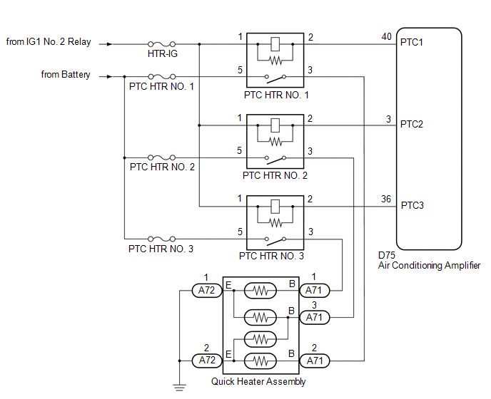
PTC Heater Circuit |
DESCRIPTION
The air conditioning amplifier sends operation signals to the PTC heater relays when the quick heater assembly operation conditions are met. Based on the signals from the air conditioning amplifier the PTC heater relays turn on, and power is supplied to the quick heater assembly installed in the air conditioning radiator assembly.
Quick Heater Assembly Operation Condition
|
Control ECU |
Condition |
|---|---|
|
Air Conditioning Amplifier |
Engine running |
|
Blower switch: on |
|
|
Temperature setting: MAX HOT |
|
|
Light control switch assembly off |
|
|
|
|
|
Ambient temperature: 10°C (50°F) or lower |
WIRING DIAGRAM
CAUTION / NOTICE / HINT
NOTICE:
Inspect the fuses for circuits related to this system before performing the following inspection procedures.
PROCEDURE
|
1. |
PERFORM ACTIVE TEST USING TECHSTREAM |
(a) Connect the Techstream to the DLC3.
(b) Turn the ignition switch to ON.
(c) Turn the Techstream on.
(d) Enter the following menus: Body Electrical / Air Conditioner / Active Test.
(e) According to the display on the Techstream, perform the Active Test.
Air Conditioner
|
Tester Display |
Measurement Item |
Control Range |
Diagnostic Note |
|---|---|---|---|
|
Heater Active Level |
Quick heater assembly |
Min.: 0 Max.: 3 |
- |
OK:
Heater Active Level changes normally.
| NG |

|
PROCEED TO NEXT SUSPECTED AREA SHOWN IN PROBLEM SYMPTOMS TABLE |
|

|
2. |
INSPECT QUICK HEATER RELAY |
(a) Remove the quick heater relay.
(b) Inspect the quick heater relay (See page
![2016 - 2020 MY Sienna [12/2015 - ]; HEATING / AIR CONDITIONING: RELAY: ON-VEHICLE INSPECTION](/t3Portal/stylegraphics/info.gif) ).
).
| NG |
|
REPLACE QUICK HEATER RELAY |
|
|
3. |
INSPECT QUICK HEATER ASSEMBLY |
(a) Remove the quick heater assembly (See page
).
(b) Inspect the quick heater assembly (See page
).
| NG |
|
|
|
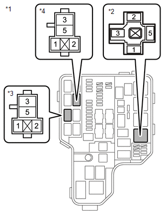
4. |
CHECK HARNESS AND CONNECTOR (QUICK HEATER RELAY - BATTERY AND IG1 NO. 2 RELAY) |
|
*1 |
Engine Room Relay Block |
|
*2 |
PTC HTR NO. 1 Relay Holder |
|
*3 |
PTC HTR NO. 2 Relay Holder |
|
*4 |
PTC HTR NO. 3 Relay Holder |
(a) Remove the quick heater relay.
(b) Measure the voltage according to the value(s) in the table below.
Standard Voltage:
|
Tester Connection |
Switch Condition |
Specified Condition |
|---|---|---|
|
PTC HTR NO. 1-5 - Body ground |
Always |
11 to 14 V |
|
PTC HTR NO. 1-1 - Body ground |
Ignition switch ON |
11 to 14 V |
|
PTC HTR NO. 2-5 - Body ground |
Always |
11 to 14 V |
|
PTC HTR NO. 2-1 - Body ground |
Ignition switch ON |
11 to 14 V |
|
PTC HTR NO. 3-5 - Body ground |
Always |
11 to 14 V |
|
PTC HTR NO. 3-1 - Body ground |
Ignition switch ON |
11 to 14 V |
| NG |
|
REPAIR OR REPLACE HARNESS OR CONNECTOR |
|
|
5. |
CHECK HARNESS AND CONNECTOR (QUICK HEATER RELAY - AIR CONDITIONING AMPLIFIER) |
(a) Remove the quick heater relay.
(b) Disconnect the D75 air conditioning amplifier connector.
(c) Measure the resistance according to the value(s) in the table below.
Standard Resistance:
|
Tester Connection |
Condition |
Specified Condition |
|---|---|---|
|
PTC HTR NO. 1-2 - D75-40 (PTC1) |
Always |
Below 1 Ω |
|
PTC HTR NO. 2-2 - D75-3 (PTC2) |
Always |
Below 1 Ω |
|
PTC HTR NO. 3-2 - D75-36 (PTC3) |
Always |
Below 1 Ω |
|
PTC HTR NO. 1-2 or D75-40 (PTC1) - Body ground |
Always |
10 kΩ or higher |
|
PTC HTR NO. 2-2 or D75-3 (PTC2) - Body ground |
Always |
10 kΩ or higher |
|
PTC HTR NO. 3-2 or D75-36 (PTC3) - Body ground |
Always |
10 kΩ or higher |
| NG |
|
REPAIR OR REPLACE HARNESS OR CONNECTOR |
|
|
6. |
CHECK HARNESS AND CONNECTOR (QUICK HEATER RELAY - QUICK HEATER ASSEMBLY) |
(a) Remove the quick heater relay.
(b) Disconnect the A71 quick heater assembly connector.
(c) Measure the resistance according to the value(s) in the table below.
Standard Resistance:
|
Tester Connection |
Condition |
Specified Condition |
|---|---|---|
|
PTC HTR NO. 1-3 - A71-2 (B) |
Always |
Below 1 Ω |
|
PTC HTR NO. 2-3 - A71-3 (B) |
Always |
Below 1 Ω |
|
PTC HTR NO. 3-3 - A71-1 (B) |
Always |
Below 1 Ω |
|
PTC HTR NO. 1-3 or A71-2 (B) - Body ground |
Always |
10 kΩ or higher |
|
PTC HTR NO. 2-3 or A71-3 (B) - Body ground |
Always |
10 kΩ or higher |
|
PTC HTR NO. 3-3 or A71-1 (B) - Body ground |
Always |
10 kΩ or higher |
| OK |
|
| NG |
|
REPAIR OR REPLACE HARNESS OR CONNECTOR |
|
|
|