| Last Modified: 08-28-2024 | 6.11:8.1.0 | Doc ID: RM100000000ZPDB |
| Model Year Start: 2017 | Model: Sienna | Prod Date Range: [08/2016 - ] |
| Title: HEATING / AIR CONDITIONING: AIR CONDITIONING SYSTEM: Rear Blower Motor Circuit; 2017 - 2020 MY Sienna [08/2016 - ] | ||
|
Rear Blower Motor Circuit |
DESCRIPTION
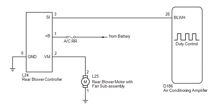
The rear blower motor is operated by signals from the air conditioning amplifier. Rear blower motor speed signals are transmitted in accordance with changes in the duty ratio.
WIRING DIAGRAM
CAUTION / NOTICE / HINT
NOTICE:
Inspect the fuses for circuits related to this system before performing the following inspection procedure.
PROCEDURE
|
1. |
PERFORM ACTIVE TEST USING TECHSTREAM |
(a) Connect the Techstream to the DLC3.
(b) Turn the ignition switch to ON.
(c) Turn the Techstream on.
(d) Enter the following menus: Body Electrical / Air Conditioner / Active Test.
(e) Check the operation by referring to the table below.
Air Conditioner
|
Tester Display |
Measurement Item |
Control Range |
Diagnostic Note |
|---|---|---|---|
|
Blower Motor Level (Rear) |
Rear blower motor |
Min.: 0 Max.: 31 |
- |
OK:
Rear blower motor operates and rear blower motor speed level changes.
Result
|
Result |
Proceed to |
|---|---|
|
NG (Rear blower motor does not operate) |
A |
|
NG (Rear blower motor operates but does not change speed) |
B |
|
OK |
C |
| B |

|
| C |
|
PROCEED TO NEXT SUSPECTED AREA SHOWN IN PROBLEM SYMPTOMS TABLE |
|

|
2. |
INSPECT REAR BLOWER W/FAN MOTOR SUB-ASSEMBLY |
(a) Disconnect the rear blower motor connector.
|
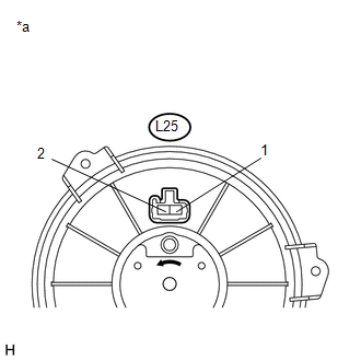
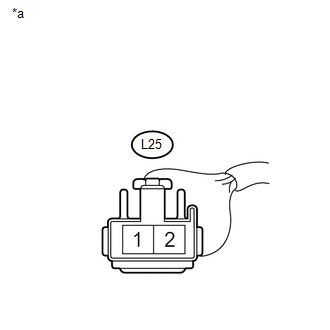
*a |
Component without harness connected (Rear Blower Motor) |
(b) Connect a battery positive (+) lead to terminal 2 and a negative (-) lead to terminal 1, then check that the rear blower motor operates smoothly.
OK:
The rear blower motor operates smoothly.
| NG |
|
|
|
3. |
CHECK HARNESS AND CONNECTOR (REAR BLOWER CONTROLLER - BODY GROUND) |
(a) Disconnect the rear blower controller connector.
|
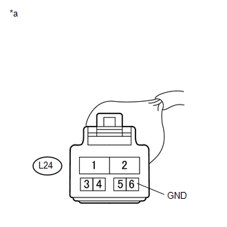
*a |
Front view of wire harness connector (to Rear Blower Controller) |
(b) Measure the resistance according to the value(s) in the table below.
Standard Resistance:
|
Tester Connection |
Condition |
Specified Condition |
|---|---|---|
|
L24-6 (GND) - Body ground |
Always |
Below 1 Ω |
| NG |
|
REPAIR OR REPLACE HARNESS OR CONNECTOR |
|
|
4. |
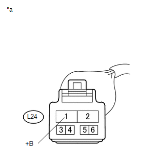
CHECK HARNESS AND CONNECTOR (REAR BLOWER CONTROLLER - BATTERY) |
|
(a) Measure the voltage according to the value(s) in the table below. Standard Voltage:
|
|
| NG |
|
REPAIR OR REPLACE HARNESS OR CONNECTOR |
|
|
5. |
CHECK HARNESS AND CONNECTOR (REAR BLOWER CONTROLLER - REAR BLOWER MOTOR) |
(a) Measure the resistance according to the value(s) in the table below.
Standard Resistance:
|
Tester Connection |
Condition |
Specified Condition |
|---|---|---|
|
L24-2 (VM) - L25-2 |
Always |
Below 1 Ω |
|
L24-2 (VM) - Body ground |
Always |
10 kΩ or higher |
| NG |
|
REPAIR OR REPLACE HARNESS OR CONNECTOR |
|
|
6. |
CHECK HARNESS AND CONNECTOR (REAR BLOWER MOTOR - BODY GROUND) |
|
(a) Measure the resistance according to the value(s) in the table below. Standard Resistance:
|
|
| NG |
|
REPAIR OR REPLACE HARNESS OR CONNECTOR |
|
|
7. |
CHECK HARNESS AND CONNECTOR (REAR BLOWER CONTROLLER - A/C AMPLIFIER) |
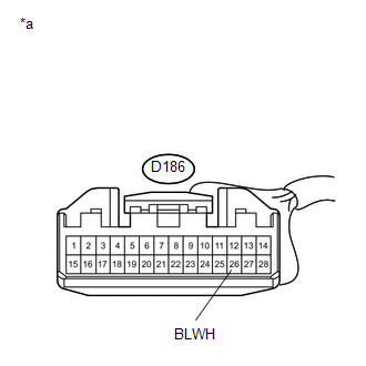
(a) Disconnect the D186 air conditioning amplifier connector.
(b) Measure the resistance according to the value(s) in the table below.
Standard Resistance:
|
Tester Connection |
Condition |
Specified Condition |
|---|---|---|
|
D186-26 (BLWH) - L24-3 (SI) |
Always |
Below 1 Ω |
|
D186-26 (BLWH) - Body ground |
Always |
10 kΩ or higher |
| NG |
|
REPAIR OR REPLACE HARNESS OR CONNECTOR |
|
|
8. |
INSPECT REAR BLOWER CONTROLLER |
(a) Reconnect the rear blower controller connector.
|
*a |
Front view of wire harness connector (to Air Conditioning Amplifier) |
(b) Measure the voltage according to the value(s) in the table below.
Standard Voltage:
|
Tester Connection |
Condition |
Specified Condition |
|---|---|---|
|
D186-26 (BLWH) - Body ground |
Always |
4.5 to 7.0 V |
| NG |
|
|
|
9. |
INSPECT AIR CONDITIONING AMPLIFIER ASSEMBLY |
(a) Reconnect the air conditioning amplifier connector.
|
(b) Remove the air conditioning amplifier with the connectors still connected. |
|
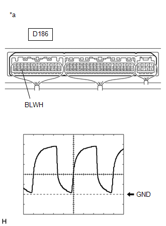
(c) Measure the waveform between terminal D186-26 (BLWH) of the air conditioning amplifier and body ground.
|
Item |
Content |
|---|---|
|
Tool Setting |
1 V/DIV., 500 μsec./DIV. |
|
Condition |
Ignition switch ON Blower switch: LO |
OK:
Waveform is as shown in the illustration.
HINT:
The waveform varies with the blower level.
| OK |
|
| NG |
|
|
|
|