| Last Modified: 08-28-2024 | 6.11:8.1.0 | Doc ID: RM100000000ZPDA |
| Model Year Start: 2017 | Model: Sienna | Prod Date Range: [08/2016 - ] |
| Title: HEATING / AIR CONDITIONING: AIR CONDITIONING SYSTEM: Blower Motor Circuit; 2017 - 2020 MY Sienna [08/2016 - ] | ||
|
Blower Motor Circuit |
DESCRIPTION
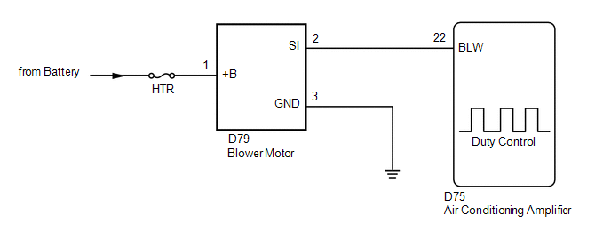
The blower motor is operated by signals from the air conditioning amplifier. Blower motor speed signals are transmitted in accordance with changes in the duty ratio.
WIRING DIAGRAM
CAUTION / NOTICE / HINT
NOTICE:
Inspect the fuses for circuits related to this system before performing the following inspection procedure.
PROCEDURE
|
1. |
PERFORM ACTIVE TEST USING TECHSTREAM |
(a) Connect the Techstream to the DLC3.
(b) Turn the ignition switch to ON.
(c) Turn the Techstream on.
(d) Enter the following menus: Body Electrical / Air Conditioner / Active Test.
(e) Check the operation by referring to the table below.
Air Conditioner
|
Tester Display |
Measurement Item |
Control Range |
Diagnostic Note |
|---|---|---|---|
|
Blower Motor Speed Level |
Blower motor with fan sub-assembly |
Min.: 0 Max.: 31 |
- |
OK:
Blower motor operates and blower motor speed level changes.
Result
|
Result |
Proceed to |
|---|---|
|
OK |
A |
|
NG (Blower motor does not operate) |
B |
|
NG (Blower motor operates but does not change speed) |
C |
| A |

|
PROCEED TO NEXT SUSPECTED AREA SHOWN IN PROBLEM SYMPTOMS TABLE |
| C |
|
|

|
2. |
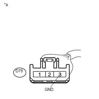
CHECK HARNESS AND CONNECTOR (BLOWER MOTOR - BODY GROUND) |
|
(a) Disconnect the blower motor connector. |
|
(b) Measure the resistance according to the value(s) in the table below.
Standard Resistance:
|
Tester Connection |
Condition |
Specified Condition |
|---|---|---|
|
D79-3 (GND) - Body ground |
Always |
Below 1 Ω |
| NG |
|
REPAIR OR REPLACE HARNESS OR CONNECTOR |
|
|
3. |
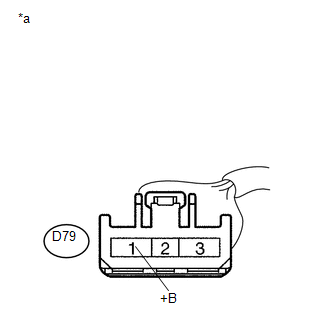
CHECK HARNESS AND CONNECTOR (BLOWER MOTOR - BATTERY) |
|
(a) Measure the voltage according to the value(s) in the table below. Standard Voltage:
|
|
| NG |
|
REPAIR OR REPLACE HARNESS OR CONNECTOR |
|
|
4. |
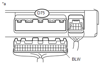
CHECK HARNESS AND CONNECTOR (BLOWER MOTOR - AIR CONDITIONING AMPLIFIER) |
(a) Disconnect the D75 air conditioning amplifier connector.
(b) Measure the resistance according to the value(s) in the table below.
Standard Resistance:
|
Tester Connection |
Condition |
Specified Condition |
|---|---|---|
|
D75-22 (BLW) - D79-2 (SI) |
Always |
Below 1 Ω |
|
D75-22 (BLW) - Body ground |
Always |
10 kΩ or higher |
| NG |
|
REPAIR OR REPLACE HARNESS OR CONNECTOR |
|
|
5. |
INSPECT BLOWER W/FAN MOTOR SUB-ASSEMBLY |
(a) Reconnect the blower motor connector.
|
(b) Measure the voltage according to the value(s) in the table below. Standard Voltage:
|
|
| NG |
|
|
|
6. |
INSPECT AIR CONDITIONING AMPLIFIER |
|
(a) Remove the air conditioning amplifier. |
|
(b) Reconnect the air conditioning amplifier connector.
(c) Turn the ignition switch to ON.
(d) Turn the blower switch LO.
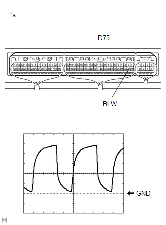
(e) Measure the waveform between terminal D75-23 (BLW) of the air conditioning amplifier and body ground.
|
Item |
Content |
|---|---|
|
Tool setting |
1 V/DIV., 500 μs/DIV. |
|
Vehicle condition |
Ignition switch ON Blower switch LO |
OK:
Waveform is as shown in the illustration.
HINT:
The waveform varies with the blower speed.
| OK |
|
| NG |
|
|
|
|