- Engine running
- A/C switch: on
- Blower switch: LO
| Last Modified: 08-28-2024 | 6.11:8.1.0 | Doc ID: RM100000000ZPCZ |
| Model Year Start: 2017 | Model: Sienna | Prod Date Range: [08/2016 - ] |
| Title: HEATING / AIR CONDITIONING: AIR CONDITIONING SYSTEM: TERMINALS OF ECU; 2017 - 2020 MY Sienna [08/2016 - ] | ||
TERMINALS OF ECU
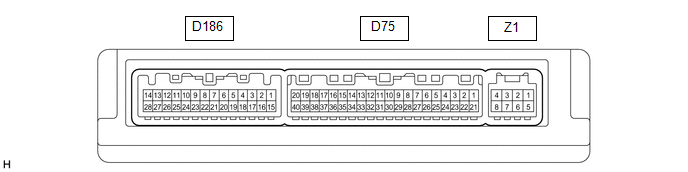
1. AIR CONDITIONING AMPLIFIER
HINT:
Check from the rear of the connector while it is connected to the air conditioning amplifier.
|
Terminal No. (Symbol) |
Wiring Color |
Terminal Description |
Condition |
Specified Condition |
|---|---|---|---|---|
|
D75-1 (IG+) - D75-14 (GND) |
R - W-B |
Power source (IG) |
Ignition switch ON |
11 to 14 V |
|
Ignition switch off |
Below 1 V |
|||
|
D75-2 (SOL+) - D75-14 (GND) |
L - W-B |
A/C compressor solenoid operation signal |
|
Pulse generation (See waveform 1) |
|
D75-3 (PTC2) - D75-14 (GND) |
Y - W-B |
Quick heater assembly operation signal |
|
Below 1 V |
|
11 to 14 V |
|||
|
D75-5 (TAM) - D75-14 (GND) |
B - W-B |
Ambient temperature sensor signal |
|
1.35 to 1.75 V |
|
0.9 to 1.2 V |
|||
|
D75-8 (LOCK) - D75-14 (GND) |
W - W-B |
A/C compressor lock sensor signal |
|
Pulse generation (See waveform 2) |
|
D75-9 (PRE) - D75-13 (SG-2) |
V - W |
A/C pressure sensor signal |
|
4.71 V or higher |
|
Below 0.74 V |
|||
|
0.74 to 4.71 V |
|||
|
D75-10 (S5-3) - D75-13 (SG-2) |
LG - W |
Power supply for A/C pressure sensor |
|
4.75 to 5.25 V |
|
Below 1 V |
|||
|
D75-11 (CANH) - D75-12 (CANL) |
G - W |
CAN communication system |
CAN communication circuit |
Pulse generation |
|
D75-13 (SG-2) - Body ground |
W - Body ground |
Ground for A/C pressure sensor, A/C ambient temperature sensor, A/C lock sensor |
Always |
Below 1 V |
|
D75-14 (GND) - Body ground |
W-B - Body ground |
Ground for main power supply |
Always |
Below 1 V |
|
D75-20 (MGC) - D75-14 (GND) |
R - W-B |
A/C compressor magnetic clutch operation signal |
|
11 to 14 V |
|
Below 1 V |
|||
|
D75-21 (B) - D75-14 (GND) |
P - W-B |
Power source (Back-up) |
Always |
11 to 14 V |
|
D75-22 (BLW) - D75-14 (GND) |
P - W-B |
Blower motor speed control signal |
Ignition switch ON Blower switch: on |
Pulse generation (See waveform 3) |
|
D75-29 (TR) - D75-34 (SG-4) |
G - W |
Cooler (room temp. sensor) thermistor signal |
|
1.8 to 2.2 V |
|
1.2 to 1.6 V |
|||
|
D75-32 (TSP) - D75-14 (GND) |
B - W-B |
Solar sensor signal (for Front passenger side) |
Ignition switch ON Solar sensor subjected to electric light |
0.8 to 4.3 V |
|
Ignition switch ON Solar sensor covered with a cloth |
Below 0.8 V |
|||
|
D75-33 (TSD) - D75-14 (GND) |
Y - W-B |
Solar sensor signal (for Driver side) |
Ignition switch ON Solar sensor subjected to electric light |
0.8 to 4.3 V |
|
Ignition switch ON Solar sensor covered with a cloth |
Below 0.8 V |
|||
|
D75-34 (SG-4) - Body ground |
W - Body ground |
Ground for cooler (room temp. sensor) thermistor |
Always |
Below 1 V |
|
D75-36 (PTC3) - D75-14 (GND) |
G - W-B |
Quick heater assembly operation signal |
|
Below 1 V |
|
11 to 14 V |
|||
|
D75-37 (LIN1) - D75-14 (GND) |
LG - W-B |
LIN communication signal |
Ignition switch ON |
Pulse generation |
|
D75-40 (PTC1) - D75-14 (GND) |
V - W-B |
Quick heater assembly operation signal |
|
Below 1 V |
|
11 to 14 V |
|||
|
D186-1 (RBUS) - D186-25 (RBUG) |
V - P |
BUS IC control signal (for Rear) |
Ignition switch ON |
Pulse generation |
|
D186-5 (TEC) - D186-7 (SGND) |
SB - G |
Rear evaporator temperature sensor signal |
|
2.0 to 2.4 V |
|
1.4 to 1.8 V |
|||
|
D186-7 (SGND) - Body ground |
G - Body ground |
Ground for rear evaporator temperature sensor |
Always |
Below 1 V |
|
D186-16 (RLIN) - D186-24 (GND2) |
L - W-B |
LIN communication signal |
Ignition switch ON |
Pulse generation |
|
D186-20 (TR) - D186-8 (RGND) |
G - Y |
Rear room temperature sensor signal |
|
1.8 to 2.2 V |
|
1.2 to 1.6 V |
|||
|
D186-24 (GND2) - Body ground |
W-B - Body ground |
Ground for power supply |
Always |
Below 1 V |
|
D186-25 (RBUG) - Body ground |
P - Body ground |
Ground for BUS IC (for Rear) |
Always |
Below 1 V |
|
D186-26 (BLWH) - D186-24 (GND2) |
L - W-B |
Rear blower motor control signal |
|
Pulse generation (See waveform 3) |
|
D186-27 (RBBU) - D186-25 (RBUG) |
GR - P |
Power supply for BUS IC (for Rear) |
Ignition switch ON |
11 to 14 V |
|
D186-28 (+B2) - D186-24 (GND2) |
P - W-B |
Power source (Back-up) |
Always |
11 to 14 V |
|
z1-2 (BUS G) - Body ground |
- |
Ground for BUS IC |
Always |
Below 1 V |
|
z1-3 (BUS) - z1-2 (BUS G) |
- |
BUS IC control signal |
Ignition switch ON |
Pulse generation |
|
z1-4 (B BUS) - z1-2 (BUS G) |
- |
Power supply for BUS IC |
Ignition switch off |
11 to 14 V |
|
z1-4 (B BUS) - z1-2 (BUS G) |
- |
Power supply for BUS IC |
Ignition switch ON |
11 to 14 V |
|
z1-5 (SGA) - Body ground |
- |
Ground for evaporator temperature sensor |
Always |
Below 1 V |
|
z1-6 (TEA) - z1-5 (SGA) |
- |
A/C evaporator temperature sensor signal |
|
1.7 to 2.1 V |
|
0.9 to 1.3 V |
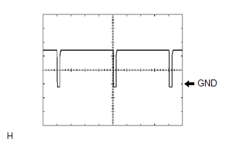
(a) Waveform 1:
|
Item |
Content |
|---|---|
|
Terminal No. |
D75-2 (SOL+) - D75-14 (GND) |
|
Tool Setting |
5 V/DIV., 500 μs/DIV. |
|
Vehicle Condition |
|
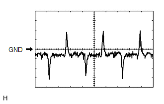
(b) Waveform 2:
|
Item |
Content |
|---|---|
|
Terminal No. |
D75-8 (LOCK) - D75-14 (GND) |
|
Tool Setting |
200 mV/DIV., 10 ms./DIV. |
|
Vehicle Condition |
|
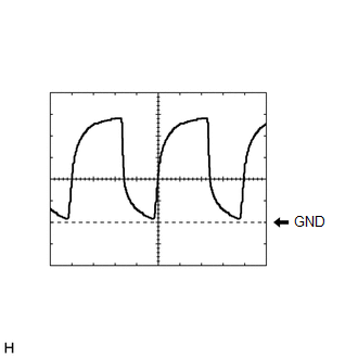
(c) Waveform 3:
|
Item |
Content |
|---|---|
|
Terminal No. |
D75-22 (BLW) - D75-14 (GND) |
|
D186-26 (BLWH) - D186-24 (GND2) |
|
|
Tool Setting |
1 V/DIV., 500 μs/DIV. |
|
Vehicle Condition |
|
2. AIR CONDITIONING CONTROL ASSEMBLY (for Front)

HINT:
Check from the rear of the connector while it is connected to the air conditioning control assembly (for front).
|
Terminal No. (Symbol) |
Wiring Color |
Terminal Description |
Condition |
Specified Condition |
|---|---|---|---|---|
|
D69-8 (LIN1) - D69-5 (GND) |
LG - W-B |
LIN communication signal |
Ignition switch ON |
Pulse generation |
|
D69-5 (GND) - Body ground |
W-B - Body ground |
Ground for front air conditioning control assembly |
Always |
Below 1 V |
|
D69-4 (IG+) - D69-5 (GND) |
R - W-B |
Power source (IG) |
Ignition switch off |
Below 1 V |
|
Ignition switch ON |
11 to 14 V |
3. NO. 2 AIR CONDITIONING CONTROL ASSEMBLY

HINT:
Check from the rear of the connector while it is connected to the No. 2 air conditioning control assembly.
|
Terminal No. (Symbol) |
Wiring Color |
Terminal Description |
Condition |
Specified Condition |
|---|---|---|---|---|
|
T7-2 (RLIN) - T7-4 (E) |
L - W-B |
LIN communication signal (for Rear) |
Ignition switch ON |
Pulse generation |
|
T7-1 (IG) - T7-4 (E) |
R - W-B |
Power source (IG) |
Ignition switch off |
Below 1 V |
|
Ignition switch ON |
11 to 14 V |
|||
|
T7-4 (E) - Body ground |
W-B - Body ground |
Ground for rear A/C control assembly |
Always |
Below 1 V |
|
|
|