| Last Modified: 08-28-2024 | 6.11:8.1.0 | Doc ID: RM100000000ZP1F |
| Model Year Start: 2017 | Model: Sienna | Prod Date Range: [08/2016 - ] |
| Title: METER / GAUGE / DISPLAY: METER / GAUGE SYSTEM: Fuel Receiver Gauge Malfunction; 2017 - 2020 MY Sienna [08/2016 - ] | ||
|
Fuel Receiver Gauge Malfunction |
DESCRIPTION
The meter CPU uses the fuel sender gauge assembly to determine the level of the fuel in the fuel tank. The resistance of the fuel sender gauge will vary between approximately 13.5 Ω with the float at the full position, and 414.5 Ω with the float at the empty position. The meter outputs battery voltage through two 820 Ω resistors that are mounted in parallel inside the meter CPU. The meter CPU measures the voltage between the variable resistor in the fuel sender gauge and the two resistors mounted in parallel in the meter. Voltage measured at this point will vary as the float of the fuel sender gauge is moved. The highest voltage observed should be approximately half of the battery voltage.
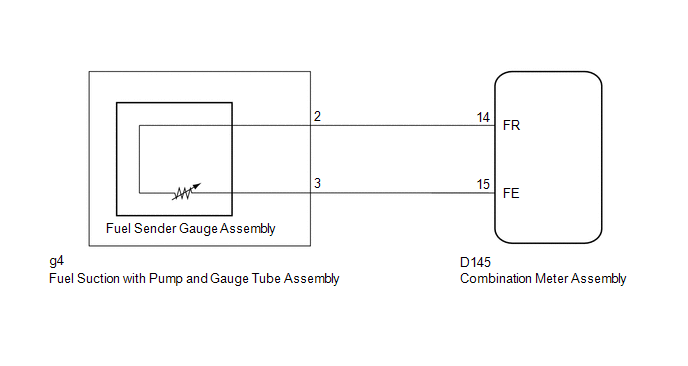
WIRING DIAGRAM
PROCEDURE
|
1. |
CHECK CAN COMMUNICATION SYSTEM |
(a) Check if a CAN communication DTC is output (See page
![2017 MY Sienna [08/2016 - 11/2017]; NETWORKING: CAN COMMUNICATION SYSTEM: DIAGNOSIS SYSTEM](/t3Portal/stylegraphics/info.gif) ).
).
Result
|
Result |
Proceed to |
|---|---|
|
CAN communication DTC is not output |
A |
|
CAN communication DTC is output |
B |
| B |

|
GO TO CAN COMMUNICATION SYSTEM
|
|

|
2. |
PERFORM ACTIVE TEST USING TECHSTREAM (FUEL METER OPERATION) |
(a) Connect the Techstream to the DLC3.
(b) Turn the ignition switch to ON.
(c) Turn the Techstream on.
(d) Enter the following menus: Body Electrical / Combination Meter / Active Test.
(e) According to the display on the Techstream, perform the Active Test.
Combination Meter
|
Tester Display |
Test part |
Control Range |
Diagnostic Note |
|---|---|---|---|
|
Fuel Meter Operation |
Fuel receiver gauge |
OFF, Sender E, Empty, Warning, 1/4, 1/2, 3/4, Full, Sender F |
Operate with IG ON and the vehicle is stopped. |
OK:
Fuel receiver gauge indication is normal.
| NG |
|
|
|
3. |
READ VALUE USING TECHSTREAM (FUEL INPUT) |
(a) Connect the Techstream to the DLC3.
(b) Turn the ignition switch to ON.
(c) Turn the Techstream on.
(d) Enter the following menus: Body Electrical / Combination Meter / Data List.
(e) According to the display on the Techstream, read the Data List.
Combination Meter
|
Tester Display |
Measurement Item/Range |
Normal Condition |
Diagnostic Note |
|---|---|---|---|
|
Fuel Input |
Fuel input signal/ Min.: 0, Max.: 127.5 |
Current fuel level displayed |
Unit: Liter |
OK:
Fuel level signal displayed on the Techstream is almost the same as fuel receiver gauge indication.
| NG |
|
|
|
4. |
CHECK HARNESS AND CONNECTOR (COMBINATION METER ASSEMBLY - FUEL SUCTION WITH PUMP AND GAUGE TUBE ASSEMBLY) |
(a) Disconnect the D145 combination meter assembly connector.
(b) Disconnect the g4 fuel suction with pump and gauge tube assembly connector.
(c) Measure the resistance according to the value(s) in the table below.
Standard Resistance:
|
Tester Connection |
Condition |
Specified Condition |
|---|---|---|
|
D145-14 (FR) - g4-2 |
Always |
Below 1 Ω |
|
D145-14 (FR) or g4-2 - Body ground |
Always |
10 kΩ or higher |
|
D145-15 (FE) - g4-3 |
Always |
Below 1 Ω |
|
D145-15 (FE) or g4-3 - Body ground |
Always |
10 kΩ or higher |
| NG |
|
REPAIR OR REPLACE HARNESS OR CONNECTOR |
|
|
5. |
INSPECT FUEL SENDER GAUGE ASSEMBLY |
(a) Remove the fuel sender gauge assembly (See page
).
(b) Inspect the fuel sender gauge assembly (See page
).
| NG |
|
|
|
6. |
INSPECT FUEL SUCTION PUMP AND GAUGE TUBE ASSEMBLY |
|
(a) Remove the fuel suction pump and gauge tube assembly (See page
|
|
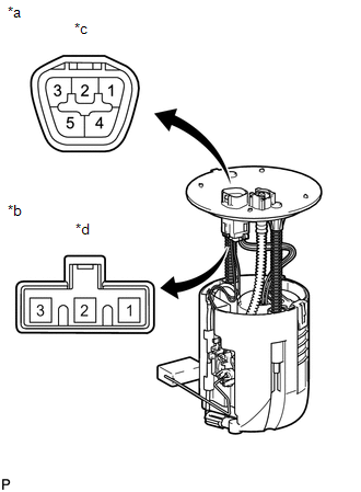
(b) Measure the resistance according to the value(s) in the table below.
Standard Resistance:
|
Tester Connection |
Condition |
Specified Condition |
|---|---|---|
|
A-2 - B-2 |
Always |
Below 1 Ω |
|
A-3 - B-1 |
Text in Illustration
|
*a |
Upper Side |
|
*b |
Lower Side (to Fuel Sender Gauge Assembly) |
|
*c |
Connector A |
|
*d |
Connector B |
| OK |
|
| NG |
|
|
|
|