| Last Modified: 08-28-2024 | 6.11:8.1.0 | Doc ID: RM100000000ZL67 |
| Model Year Start: 2017 | Model: Sienna | Prod Date Range: [08/2016 - ] |
| Title: THEFT DETERRENT / KEYLESS ENTRY: THEFT DETERRENT SYSTEM: Security Horn Circuit; 2017 - 2020 MY Sienna [08/2016 - ] | ||
|
Security Horn Circuit |
DESCRIPTION
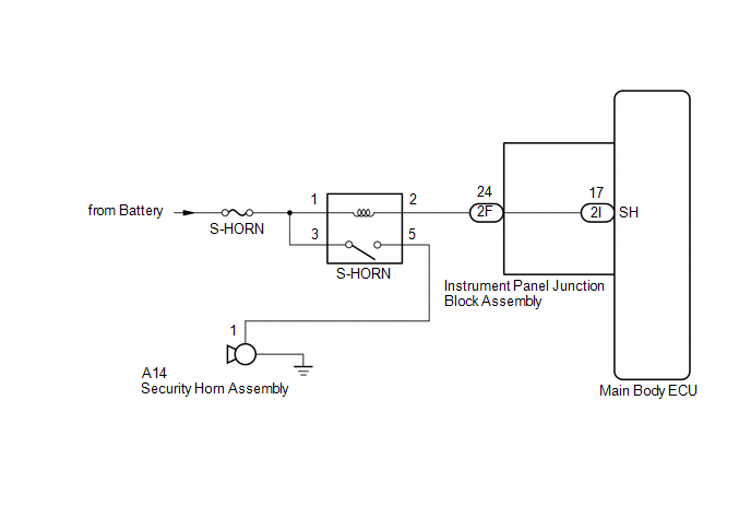
When the theft deterrent system is switched from the armed state to the alarm sounding state, the main body ECU controls the security horn assembly.
WIRING DIAGRAM
CAUTION / NOTICE / HINT
NOTICE:
Inspect the fuses for circuits related to this system before performing the following inspection procedure.
PROCEDURE
|
1. |
PERFORM ACTIVE TEST USING TECHSTREAM |
(a) Connect the Techstream to the DLC3.
(b) Turn the ignition switch to ON.
(c) Turn the Techstream on.
(d) Select the item below in the Active Test and then check that the security horn assembly operates.
Main Body
|
Tester Display |
Test Part |
Control Range |
Diagnostic Note |
|---|---|---|---|
|
Security Horn |
Security horn |
ON/OFF |
- |
OK:
The security horn assembly sounds and stops correctly when operated through the Techstream.
| OK |

|
PROCEED TO NEXT SUSPECTED AREA SHOWN IN PROBLEM SYMPTOMS TABLE |
|

|
2. |
INSPECT SECURITY HORN ASSEMBLY |
(a) Remove the security horn assembly (See page
![2017 - 2020 MY Sienna [08/2016 - ]; THEFT DETERRENT / KEYLESS ENTRY: SECURITY HORN ASSEMBLY: REMOVAL](/t3Portal/stylegraphics/info.gif) ).
).
(b) Inspect the security horn assembly (See page
).
| NG |
|
|
|
3. |
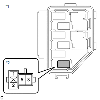
INSPECT S-HORN RELAY |
(a) Remove the S-HORN relay from the No. 3 relay block.
(b) Inspect the S-HORN relay (See page
).
| NG |
|
REPLACE S-HORN RELAY |
|
|
4. |
INSPECT INSTRUMENT PANEL JUNCTION BLOCK ASSEMBLY |
|
(a) Remove the main body ECU (See page
|
|
(b) Disconnect the instrument panel junction block assembly connector.
(c) Measure the resistance according to the value(s) in the table below.
Standard Resistance:
|
Tester Connection |
Condition |
Specified Condition |
|---|---|---|
|
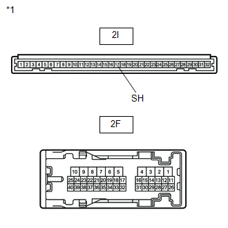
2F-24 - 2I-17 (SH) |
Always |
Below 1 Ω |
| NG |
|
|
|
5. |
CHECK HARNESS AND CONNECTOR (BATTERY - S-HORN RELAY) |
|
(a) Measure the voltage according to the value(s) in the table below. Standard Voltage:
|
|

| NG |
|
REPAIR OR REPLACE HARNESS OR CONNECTOR |
|
|
6. |
CHECK HARNESS AND CONNECTOR (S-HORN RELAY - SECURITY HORN ASSEMBLY) |
|
(a) Measure the resistance according to the value(s) in the table below. Standard Resistance:
|
|

| NG |
|
REPAIR OR REPLACE HARNESS OR CONNECTOR |
|
|
7. |
CHECK HARNESS AND CONNECTOR (S-HORN RELAY - INSTRUMENT PANEL JUNCTION BLOCK ASSEMBLY) |
|
(a) Measure the resistance according to the value(s) in the table below. Standard Resistance:
|
|
| OK |
|
| NG |
|
REPAIR OR REPLACE HARNESS OR CONNECTOR |
|
|
|