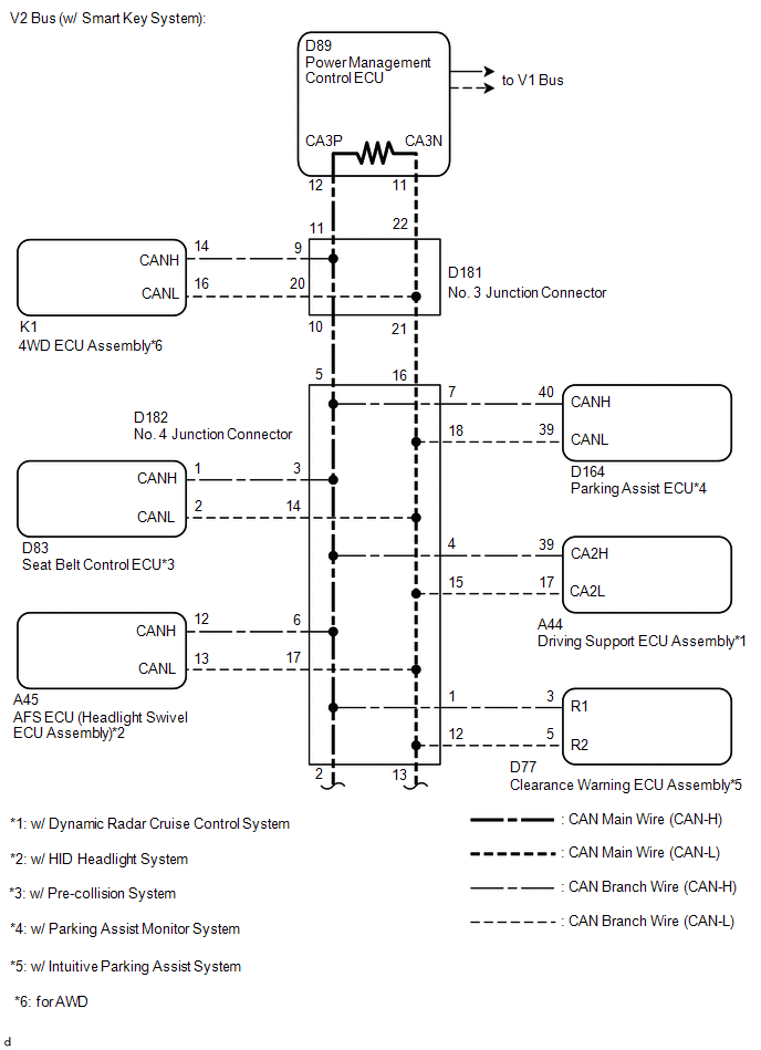
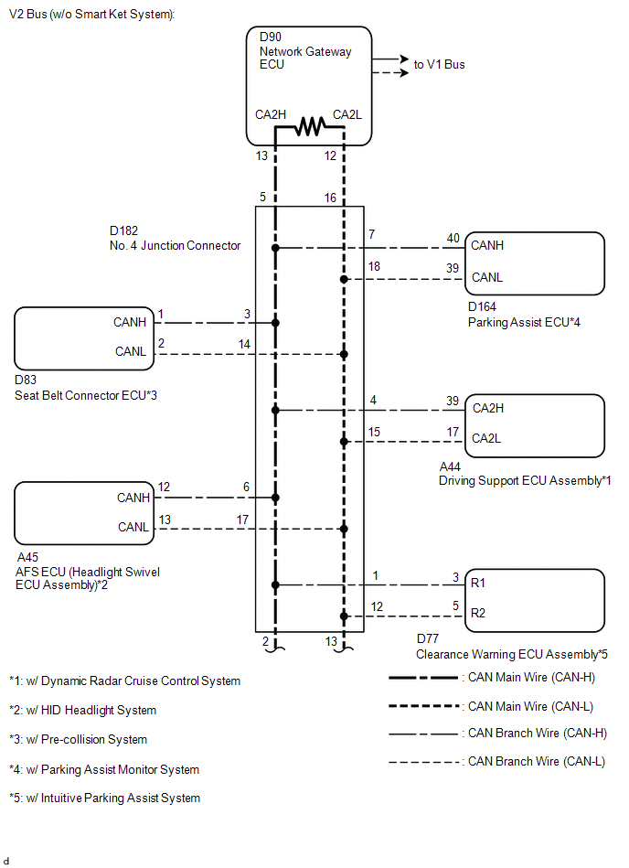
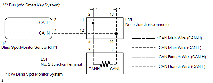
- V2 bus circuit
- Power management control ECU*1 or network gateway ECU*2 main wire or connector
- Seat belt control ECU branch wire or connector*3
- AFS ECU (headlight swivel ECU assembly) branch wire or connector*4
- Parking assist ECU branch wire or connector*5
- Driving support ECU assembly branch wire or connector*6
- Clearance warning ECU assembly branch wire or connector*7
- Blind spot monitor sensor RH branch wire or connector*8
- Power management control ECU*1
- Network gateway ECU*2
- Seat belt control ECU*3
- AFS ECU (headlight swivel ECU assembly)*4
- Parking assist ECU*5
- Driving support ECU assembly*6
- Clearance warning ECU assembly*7
- Blind spot monitor sensor RH*8
- 4WD ECU assembly*9*1
- No. 4 junction connector
- No. 5 junction connector
- No. 2 junction terminal
- No. 3 junction connector*1
| Last Modified: 08-28-2024 | 6.11:8.1.0 | Doc ID: RM100000000Z14N |
| Model Year Start: 2017 | Model: Sienna | Prod Date Range: [08/2016 - 11/2017] |
| Title: NETWORKING: CAN COMMUNICATION SYSTEM: U1002 (CAN No. 2 BUS); Lost Communication with Gateway Module (Network Gateway ECU); 2017 MY Sienna [08/2016 - 11/2017] | ||
|
DTC |
U1002 (CAN No. 2 BUS) |
Lost Communication with Gateway Module (Network Gateway ECU) |
DESCRIPTION
If 2 or more DTCs are output during the DTC check, one side of the CAN branch wire may be open (One side of the CANH [branch wire]/CANL [branch wire] of the ECU and/or sensor is open).
|
DTC Code |
Symptoms |
Trouble Area |
|---|---|---|
|
U1002 (CAN No. 2 BUS) |
Lost communication with the gateway module (network gateway ECU). |
|
- *1: w/ Smart Key System
- *2: w/o Smart Key System
- *3: w/ Pre-Collision System
- *4: w/ HID Headlight System
- *5: w/ Parking Assist Monitor System
- *6: w/ Dynamic Radar Cruise Control System
- *7: w/ Intuitive Parking Assist System
- *8: w/ Blind Spot Monitor System
- *9: for AWD
WIRING DIAGRAM

CAUTION / NOTICE / HINT
NOTICE:
- Turn the ignition switch off before measuring the resistances between CAN bus main wires and between CAN bus branch wires.
- Turn the ignition switch off before inspecting CAN bus wires for a ground short.
- After the ignition switch is turned off, check that the key reminder warning system and light reminder warning system are not operating.
- Before measuring the resistance, leave the vehicle as is for at least 1 minute and do not operate the ignition switch, any other switches or the doors. If any doors need to be opened in order to check connectors, open the doors and leave them open.
HINT:
- Operating the ignition switch, any other switches or a door triggers related ECU and sensor communication on the CAN. This communication will cause the resistance value to change.
- Even after DTCs are cleared, if a DTC is stored again after driving the vehicle for a while, the malfunction may be occurring due to vibration of the vehicle. In such a case, wiggling the ECUs or wire harness while performing the inspection below may help determine the cause of the malfunction.
PROCEDURE
|
1. |
PRECAUTION |
NOTICE:
After turning the ignition switch off, waiting time may be required before disconnecting the cable from the battery terminal. Therefore, make sure to read the disconnecting the cable from the battery terminal notice before proceeding with work (See page
![2017 - 2020 MY Sienna [08/2016 - ]; INTRODUCTION: REPAIR INSTRUCTION: PRECAUTION](/t3Portal/stylegraphics/info.gif) ).
).
|

|
2. |
DISCONNECT CABLE FROM NEGATIVE BATTERY TERMINAL |
(a) Disconnect the cable from the negative (-) battery terminal before measuring the resistances of the main wire and the branch wire.
CAUTION:
Wait at least 90 seconds after disconnecting the cable from the negative (-) battery terminal to disable the SRS system.
NOTICE:
When disconnecting the cable, some systems need to be initialized after the cable is reconnected (See page
)
Result
|
Result |
Proceed to |
|---|---|
|
w/ Smart Key System |
A |
|
w/o Smart Key System |
B |
| B |

|
|
|
3. |
CHECK CAN BUS WIRE (MAIN WIRE FOR DISCONNECTION, BUS LINE FOR SHORT CIRCUIT) |
|
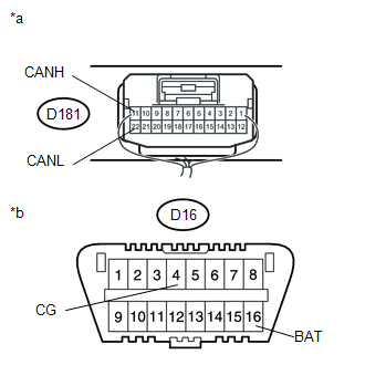
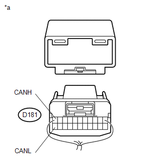
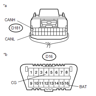
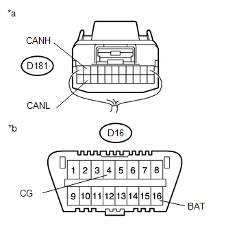
*a |
Junction connector with harness connected (No. 3 Junction Connector) |
|
*b |
Front view of DLC3 |
(a) Measure the resistance according to the value(s) in the table below.
Standard Resistance:
|
Tester Connection |
Switch Condition |
Specified Condition |
Resistance Malfunction |
|---|---|---|---|
|
D181-11 (CANH) - D181-22 (CANL) |
Ignition switch off |
54 to 69 Ω |
Below 53 Ω: Short in line |
|
Ignition switch off |
70 Ω or higher: Open in CAN main bus line |
||
|
D181-11 (CANH) - D16-16 (BAT) |
Ignition switch off |
6 kΩ or higher |
Below 6 kΩ: +B short |
|
D181-22 (CANL) - D16-16 (BAT) |
Ignition switch off |
6 kΩ or higher |
Below 6 kΩ: +B short |
|
D181-11 (CANH) - D16-4 (CG) |
Ignition switch off |
200 Ω or higher |
Below 200 Ω: Ground short |
|
D181-22 (CANL) - D16-4 (CG) |
Ignition switch off |
200 Ω or higher |
Below 200 Ω: Ground short |
Result
|
Result |
Proceed to |
|---|---|
|
NG - Open in CAN main wire |
A |
|
NG - Short in line - +B short - Ground short |
B |
|
OK |
C |
| B |
|
| C |
|
|
|
4. |
CHECK FOR OPEN IN CAN BUS MAIN WIRE (NO. 3 JUNCTION CONNECTOR - POWER MANAGEMENT CONTROL ECU) |
|
(a) Disconnect the No. 3 junction connector connector. |
|
(b) Measure the resistance according to the value(s) in the table below.
Standard Resistance:
|
Tester Connection |
Switch Condition |
Specified Condition |
|---|---|---|
|
D181-11 (CANH) - D181-22 (CANL) |
Ignition switch off |
108 to 132 Ω |
Result
|
Result |
Proceed to |
|---|---|
|
NG |
A |
|
OK |
B |
| B |
|
|
|
5. |
CONNECT CONNECTOR |
(a) Reconnect the D181 No. 3 junction connector connector.
|
|
6. |
CHECK FOR OPEN IN CAN BUS MAIN WIRE (POWER MANAGEMENT CONTROL ECU - NO. 4 JUNCTION CONNECTOR) |
|
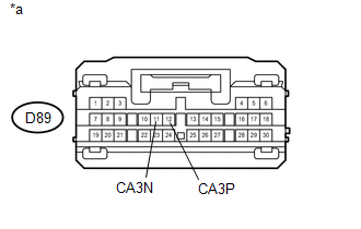
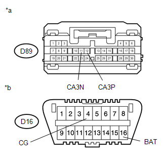
*a |
Front view of wire harness connector (to Power Management Control ECU) |
(a) Disconnect the power management control ECU connector.
(b) Measure the resistance according to the value(s) in the table below.
Standard Resistance:
|
Tester Connection |
Switch Condition |
Specified Condition |
|---|---|---|
|
D89-12 (CA3P) - D89-11 (CA3N) |
Ignition switch off |
108 to 132 Ω |
| OK |
|
| NG |
|
REPAIR OR REPLACE CAN MAIN WIRE CONNECTED TO POWER MANAGEMENT CONTROL ECU (POWER MANAGEMENT CONTROL ECU - NO. 3 JUNCTION CONNECTOR) |
|
7. |
CHECK FOR OPEN IN CAN BUS MAIN WIRE (NO. 3 JUNCTION CONNECTOR - NO. 4 JUNCTION CONNECTOR) |
|
(a) Disconnect the No. 3 junction connector connector. |
|
(b) Measure the resistance according to the value(s) in the table below.
Standard Resistance:
|
Tester Connection |
Switch Condition |
Specified Condition |
|---|---|---|
|
D181-11 (CANH) - D181-22 (CANL) |
Ignition switch off |
108 to 132 Ω |
Result
|
Result |
Proceed to |
|---|---|
|
NG |
A |
|
OK |
B |
| B |
|
REPLACE NO. 3 JUNCTION CONNECTOR |
|
|
8. |
CONNECT CONNECTOR |
(a) Reconnect the D181 No. 3 junction connector connector.
|
|
9. |
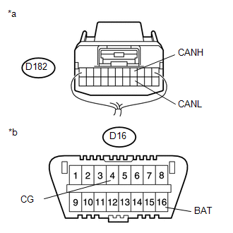
CHECK FOR OPEN IN CAN BUS MAIN WIRE (NO. 4 JUNCTION CONNECTOR - NO. 5 JUNCTION CONNECTOR) |
|
(a) Disconnect the No. 4 junction connector connector. |
|
(b) Measure the resistance according to the value(s) in the table below.
Standard Resistance:
|
Tester Connection |
Switch Condition |
Specified Condition |
|---|---|---|
|
D182-2 (CANH) - D182-13 (CANL) |
Ignition switch off |
108 to 132 Ω |
Result
|
Result |
Proceed to |
|---|---|
|
NG |
A |
|
OK |
B |
| B |
|
REPLACE NO. 4 JUNCTION CONNECTOR |
|
|
10. |
CONNECT CONNECTOR |
(a) Reconnect the D182 No. 4 junction connector connector.
|
|
11. |
CHECK FOR OPEN IN CAN BUS MAIN WIRE (NO. 4 JUNCTION CONNECTOR - NO. 5 JUNCTION CONNECTOR) |
|
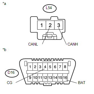
(a) Disconnect the No. 5 junction connector connector. |
|
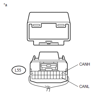
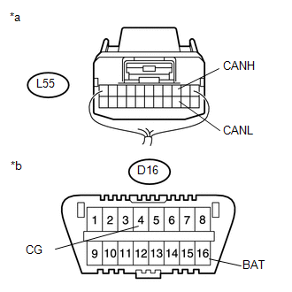
(b) Measure the resistance according to the value(s) in the table below.
Standard Resistance:
|
Tester Connection |
Switch Condition |
Specified Condition |
|---|---|---|
|
L55-2 (CANH) - L55-13 (CANL) |
Ignition switch off |
108 to 132 Ω |
| NG |
|
REPAIR OR REPLACE CAN MAIN WIRE OR CONNECTOR (NO. 4 JUNCTION CONNECTOR - NO. 5 JUNCTION CONNECTOR) |
|
|
12. |
CHECK FOR OPEN IN CAN BUS MAIN WIRE (NO. 5 JUNCTION CONNECTOR SIDE) |
|
(a) Measure the resistance according to the value(s) in the table below. Standard Resistance:
|
|

| NG |
|
REPLACE NO. 5 JUNCTION CONNECTOR |
|
|
13. |
CONNECT CONNECTOR |
(a) Reconnect the L55 No. 5 junction connector connector.
|
|
14. |
CHECK FOR OPEN IN CAN BUS MAIN WIRE (NO. 2 JUNCTION TERMINAL - NO. 5 JUNCTION CONNECTOR) |
(a) Disconnect the No. 2 junction terminal connector.
|
(b) Measure the resistance according to the value(s) in the table below. Standard Resistance:
|
|
| OK |
|
REPLACE NO. 2 JUNCTION TERMINAL |
| NG |
|
REPAIR OR REPLACE CAN MAIN WIRE OR CONNECTOR (NO. 2 JUNCTION TERMINAL - NO. 5 JUNCTION CONNECTOR) |
|
15. |
CHECK FOR SHORT IN CAN BUS WIRES (NO. 3 JUNCTION CONNECTOR - POWER MANAGEMENT CONTROL ECU) |
|
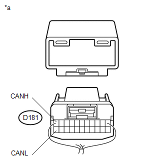
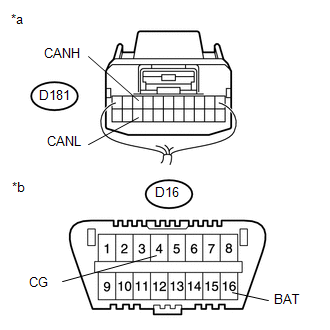
*a |
Rear view of wire harness connector (to No. 3 Junction Connector) |
|
*b |
Front view of DLC3 |
(a) Disconnect the No. 3 junction connector connector.
(b) Measure the resistance according to the value(s) in the table below.
Standard Resistance:
|
Tester Connection |
Switch Condition |
Specified Condition |
|---|---|---|
|
D181-11 (CANH) - D181-22 (CANL) |
Ignition switch off |
108 to 132 Ω |
|
D181-11 (CANH) - D16-4 (CG) |
Ignition switch off |
200 Ω or higher |
|
D181-22 (CANL) - D16-4 (CG) |
Ignition switch off |
200 Ω or higher |
|
D181-11 (CANH) - D16-16 (BAT) |
Ignition switch off |
6 kΩ or higher |
|
D181-22 (CANL) - D16-16 (BAT) |
Ignition switch off |
6 kΩ or higher |
| NG |
|
|
|
16. |
CHECK FOR SHORT IN CAN BUS WIRES (NO. 3 JUNCTION CONNECTOR - 4WD ECU ASSEMBLY) |
|
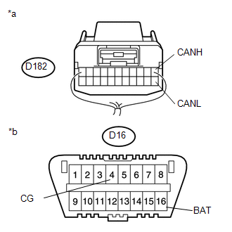
*a |
Rear view of wire harness connector (to No. 3 Junction Connector) |
|
*b |
Front view of DLC3 |
HINT:
Except AWD without smart key system, go to step 17.
(a) Measure the resistance according to the value(s) in the table below.
Standard Resistance:
|
Tester Connection |
Switch Condition |
Specified Condition |
|---|---|---|
|
D181-9 (CANH) - D181-20 (CANL) |
Ignition switch off |
200 Ω or higher |
|
D181-9 (CANH) - D16-4 (CG) |
Ignition switch off |
200 Ω or higher |
|
D181-20 (CANL) - D16-4 (CG) |
Ignition switch off |
200 Ω or higher |
|
D181-9 (CANH) - D16-16 (BAT) |
Ignition switch off |
6 kΩ or higher |
|
D181-20 (CANL) - D16-16 (BAT) |
Ignition switch off |
6 kΩ or higher |
| NG |
|
|
|
17. |
CHECK FOR SHORT IN CAN BUS WIRES (NO. 3 JUNCTION CONNECTOR SIDE) |
|
(a) Measure the resistance according to the value(s) in the table below. Standard Resistance:
Result
|
|
| B |
|
REPLACE NO. 3 JUNCTION CONNECTOR |
|
|
18. |
CONNECT CONNECTOR |
(a) Reconnect the D181 No. 3 junction connector connector.
|
|
19. |
CHECK FOR SHORT IN CAN BUS WIRES (NO. 4 JUNCTION CONNECTOR - NO. 3 JUNCTION CONNECTOR) |
|
(a) Disconnect the No. 4 junction connector connector. |
|
(b) Measure the resistance according to the value(s) in the table below.
Standard Resistance:
|
Tester Connection |
Switch Condition |
Specified Condition |
|---|---|---|
|
D182-5 (CANH) - D182-16 (CANL) |
Ignition switch off |
108 to 132 Ω |
|
D182-5 (CANH) - D16-4 (CG) |
Ignition switch off |
200 Ω or higher |
|
D182-16 (CANL) - D16-4 (CG) |
Ignition switch off |
200 Ω or higher |
|
D182-5 (CANH) - D16-16 (BAT) |
Ignition switch off |
6 kΩ or higher |
|
D182-16 (CANL) - D16-16 (BAT) |
Ignition switch off |
6 kΩ or higher |
| NG |
|
REPAIR OR REPLACE CAN MAIN WIRE OR CONNECTOR (NO. 4 JUNCTION CONNECTOR - NO. 3 JUNCTION CONNECTOR) |
|
|
20. |
CHECK FOR SHORT IN CAN BUS WIRES (NO. 4 JUNCTION CONNECTOR - CLEARANCE WARNING ECU ASSEMBLY) |
HINT:
For vehicle without intuitive parking assist system, go to step 21.
|
*a |
Rear view of wire harness connector (to No. 4 Junction Connector) |
|
*b |
Front view of DLC3 |
(a) Measure the resistance according to the value(s) in the table below.
Standard Resistance:
|
Tester Connection |
Switch Condition |
Specified Condition |
|---|---|---|
|
D182-1 (CANH) - D182-12 (CANL) |
Ignition switch off |
200 Ω or higher |
|
D182-1 (CANH) - D16-4 (CG) |
Ignition switch off |
200 Ω or higher |
|
D182-12 (CANL) - D16-4 (CG) |
Ignition switch off |
200 Ω or higher |
|
D182-1 (CANH) - D16-16 (BAT) |
Ignition switch off |
6 kΩ or higher |
|
D182-12 (CANL) - D16-16 (BAT) |
Ignition switch off |
6 kΩ or higher |
| NG |
|
|
|
21. |
CHECK FOR SHORT IN CAN BUS WIRES (NO. 4 JUNCTION CONNECTOR - SEAT BELT CONTROL ECU) |
|
*a |
Rear view of wire harness connector (to No. 4 Junction Connector) |
|
*b |
Front view of DLC3 |
HINT:
For vehicle without pre-collision system, go to step 22.
(a) Measure the resistance according to the value(s) in the table below.
Standard Resistance:
|
Tester Connection |
Switch Condition |
Specified Condition |
|---|---|---|
|
D182-3 (CANH) - D182-14 (CANL) |
Ignition switch off |
200 Ω or higher |
|
D182-3 (CANH) - D16-4 (CG) |
Ignition switch off |
200 Ω or higher |
|
D182-14 (CANL) - D16-4 (CG) |
Ignition switch off |
200 Ω or higher |
|
D182-3 (CANH) - D16-16 (BAT) |
Ignition switch off |
6 kΩ or higher |
|
D182-14 (CANL) - D16-16 (BAT) |
Ignition switch off |
6 kΩ or higher |
| NG |
|
|
|
22. |
CHECK FOR SHORT IN CAN BUS WIRES (NO. 4 JUNCTION CONNECTOR - DRIVING SUPPORT ECU ASSEMBLY) |
|
*a |
Rear view of wire harness connector (to No. 4 Junction Connector) |
|
*b |
Front view of DLC3 |
HINT:
For vehicle without dynamic radar cruise control system, go to step 23.
(a) Measure the resistance according to the value(s) in the table below.
Standard Resistance:
|
Tester Connection |
Switch Condition |
Specified Condition |
|---|---|---|
|
D182-4 (CANH) - D182-15 (CANL) |
Ignition switch off |
200 Ω or higher |
|
D182-4 (CANH) - D16-4 (CG) |
Ignition switch off |
200 Ω or higher |
|
D182-15 (CANL) - D16-4 (CG) |
Ignition switch off |
200 Ω or higher |
|
D182-4 (CANH) - D16-16 (BAT) |
Ignition switch off |
6 kΩ or higher |
|
D182-15 (CANL) - D16-16 (BAT) |
Ignition switch off |
6 kΩ or higher |
| NG |
|
|
|
23. |
CHECK FOR SHORT IN CAN BUS WIRES (NO. 4 JUNCTION CONNECTOR - AFS ECU (HEADLIGHT SWIVEL ECU ASSEMBLY)) |

|
*a |
Rear view of wire harness connector (to No. 4 Junction Connector) |
|
*b |
Front view of DLC3 |
HINT:
For vehicle without HID headlight system, go to step 24.
(a) Measure the resistance according to the value(s) in the table below.
Standard Resistance:
|
Tester Connection |
Switch Condition |
Specified Condition |
|---|---|---|
|
D182-6 (CANH) - D182-17 (CANL) |
Ignition switch off |
200 Ω or higher |
|
D182-6 (CANH) - D16-4 (CG) |
Ignition switch off |
200 Ω or higher |
|
D182-17 (CANL) - D16-4 (CG) |
Ignition switch off |
200 Ω or higher |
|
D182-6 (CANH) - D16-16 (BAT) |
Ignition switch off |
6 kΩ or higher |
|
D182-17 (CANL) - D16-16 (BAT) |
Ignition switch off |
6 kΩ or higher |
| NG |
|
|
|
24. |
CHECK FOR SHORT IN CAN BUS WIRES (NO. 4 JUNCTION CONNECTOR - PARKING ASSIST ECU) |
|
*a |
Rear view of wire harness connector (to No. 4 Junction Connector) |
|
*b |
Front view of DLC3 |
HINT:
For vehicle without parking assist monitor system, go to step 25.
(a) Measure the resistance according to the value(s) in the table below.
Standard Resistance:
|
Tester Connection |
Switch Condition |
Specified Condition |
|---|---|---|
|
D182-7 (CANH) - D182-18 (CANL) |
Ignition switch off |
200 Ω or higher |
|
D182-7 (CANH) - D16-4 (CG) |
Ignition switch off |
200 Ω or higher |
|
D182-18 (CANL) - D16-4 (CG) |
Ignition switch off |
200 Ω or higher |
|
D182-7 (CANH) - D16-16 (BAT) |
Ignition switch off |
6 kΩ or higher |
|
D182-18 (CANL) - D16-16 (BAT) |
Ignition switch off |
6 kΩ or higher |
| NG |
|
|
|
25. |
CHECK FOR SHORT IN CAN BUS WIRES (NO. 4 JUNCTION CONNECTOR SIDE) |
|
(a) Measure the resistance according to the value(s) in the table below. Standard Resistance:
Result
|
|
| B |
|
REPLACE NO. 4 JUNCTION CONNECTOR |
|
|
26. |
CONNECT CONNECTOR |
(a) Reconnect the D182 No. 4 junction connector connector.
|
|
27. |
CHECK FOR SHORT IN CAN BUS WIRES (NO. 5 JUNCTION CONNECTOR - NO. 4 JUNCTION CONNECTOR) |
|
(a) Disconnect the No. 5 junction connector connector. |
|
(b) Measure the resistance according to the value(s) in the table below.
Standard Resistance:
|
Tester Connection |
Switch Condition |
Specified Condition |
|---|---|---|
|
L55-2 (CANH) - L55-13 (CANL) |
Ignition switch off |
108 to 132 Ω |
|
L55-2 (CANH) - D16-4 (CG) |
Ignition switch off |
200 Ω or higher |
|
L55-13 (CANL) - D16-4 (CG) |
Ignition switch off |
200 Ω or higher |
|
L55-2 (CANH) - D16-16 (BAT) |
Ignition switch off |
6 kΩ or higher |
|
L55-13 (CANL) - D16-16 (BAT) |
Ignition switch off |
6 kΩ or higher |
| NG |
|
REPAIR OR REPLACE CAN MAIN WIRE OR CONNECTOR (NO. 5 JUNCTION CONNECTOR - NO. 4 JUNCTION CONNECTOR) |
|
|
28. |
CHECK FOR SHORT IN CAN BUS WIRES (NO. 5 JUNCTION CONNECTOR - BLIND SPOT MONITOR SENSOR RH) |
HINT:
For vehicle without blind spot monitor system, go to 29.
|
(a) Measure the resistance according to the value(s) in the table below. Standard Resistance:
|
|

| NG |
|
|
|
29. |
CHECK FOR SHORT IN CAN BUS WIRES (NO. 5 JUNCTION CONNECTOR SIDE) |
|
(a) Measure the resistance according to the value(s) in the table below. Standard Resistance:
|
|
| NG |
|
REPLACE NO. 5 JUNCTION CONNECTOR |
|
|
30. |
CONNECT CONNECTOR |
(a) Reconnect the L55 No. 5 junction connector connector.
|
|
31. |
CHECK FOR SHORT IN CAN BUS WIRES (NO. 2 JUNCTION TERMINAL - NO. 5 JUNCTION CONNECTOR) |
(a) Disconnect the No. 2 junction terminal connector.
|
(b) Measure the resistance according to the value(s) in the table below. Standard Resistance:
|
|
| OK |
|
REPLACE NO. 2 JUNCTION TERMINAL |
| NG |
|
REPAIR OR REPLACE CAN MAIN WIRE CONNECTED TO JUNCTION TERMINAL (NO. 2 JUNCTION TERMINAL - NO. 5 JUNCTION CONNECTOR) |
|
32. |
CONNECT CONNECTOR |
(a) Reconnect the D181 No. 3 junction connector connector.
|
|
33. |
CHECK FOR SHORT IN CAN BUS WIRES (POWER MANAGEMENT CONTROL ECU) |
|
*a |
Front view of wire harness connector (to Power Management Control ECU) |
|
*b |
Front view of DLC3 |
(a) Disconnect the power management control ECU connector.
(b) Measure the resistance according to the value(s) in the table below.
Standard Resistance:
|
Tester Connection |
Switch Condition |
Specified Condition |
|---|---|---|
|
D89-12 (CA3P) - D89-11 (CA3N) |
Ignition switch off |
108 to 132 Ω |
|
D89-12 (CA3P) - D16-4 (CG) |
Ignition switch off |
200 Ω or higher |
|
D89-11 (CA3N) - D16-4 (CG) |
Ignition switch off |
200 Ω or higher |
|
D89-12 (CA3P) - D16-16 (BAT) |
Ignition switch off |
6 kΩ or higher |
|
D89-11 (CA3N) - D16-16 (BAT) |
Ignition switch off |
6 kΩ or higher |
| OK |
|
| NG |
|
REPAIR OR REPLACE CAN MAIN WIRE CONNECTED TO POWER MANAGEMENT CONTROL ECU (CAN-H, CAN-L) |
|
34. |
CONNECT CONNECTOR |
(a) Reconnect the D181 No. 3 junction connector connector.
|
|
35. |
CHECK FOR SHORT IN CAN BUS WIRES (4WD ECU ASSEMBLY) |
|
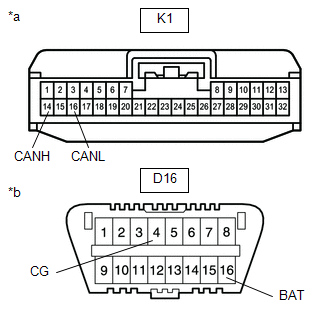
*a |
Front view of wire harness connector (to 4WD ECU Assembly) |
|
*b |
Front view of DLC3 |
(a) Disconnect the 4WD ECU assembly connector.
(b) Measure the resistance according to the value(s) in the table below.
Standard Resistance:
|
Tester Connection |
Switch Condition |
Specified Condition |
|---|---|---|
|
K1-14 (CANH) - K1-16 (CANL) |
Ignition switch off |
54 to 69 Ω |
|
K1-14 (CANH) - D16-4 (CG) |
Ignition switch off |
200 Ω or higher |
|
K1-16 (CANL) - D16-4 (CG) |
Ignition switch off |
200 Ω or higher |
|
K1-14 (CANH) - D16-16 (BAT) |
Ignition switch off |
6 kΩ or higher |
|
K1-16 (CANL) - D16-16 (BAT) |
Ignition switch off |
6 kΩ or higher |
| OK |
|
| NG |
|
REPAIR OR REPLACE CAN BRANCH WIRE CONNECTED TO CLEARANCE WARNING ECU ASSEMBLY (CAN-H, CAN-L) |
|
36. |
CONNECT CONNECTOR |
(a) Reconnect the D182 No. 4 junction connector connector.
|
|
37. |
CHECK FOR SHORT IN CAN BUS WIRES (CLEARANCE WARNING ECU ASSEMBLY) |
|
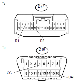
*a |
Front view of wire harness connector (to Clearance Warning ECU Assembly) |
|
*b |
Front view of DLC3 |
(a) Disconnect the clearance warning ECU assembly connector.
(b) Measure the resistance according to the value(s) in the table below.
Standard Resistance:
|
Tester Connection |
Switch Condition |
Specified Condition |
|---|---|---|
|
D77-3 (R1) - D77-5 (R2) |
Ignition switch off |
54 to 69 Ω |
|
D77-3 (R1) - D16-4 (CG) |
Ignition switch off |
200 Ω or higher |
|
D77-5 (R2) - D16-4 (CG) |
Ignition switch off |
200 Ω or higher |
|
D77-3 (R1) - D16-16 (BAT) |
Ignition switch off |
6 kΩ or higher |
|
D77-5 (R2) - D16-16 (BAT) |
Ignition switch off |
6 kΩ or higher |
| OK |
|
| NG |
|
REPAIR OR REPLACE CAN BRANCH WIRE CONNECTED TO CLEARANCE WARNING ECU ASSEMBLY (CAN-H, CAN-L) |
|
38. |
CONNECT CONNECTOR |
(a) Reconnect the D182 No. 4 junction connector connector.
|
|
39. |
CHECK FOR SHORT IN CAN BUS WIRES (SEAT BELT CONTROL ECU) |
|
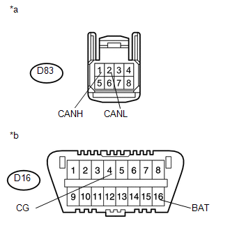
*a |
Front view of wire harness connector (to Seat Belt Control ECU) |
|
*b |
Front view of DLC3 |
(a) Disconnect the seat belt control ECU connector.
(b) Measure the resistance according to the value(s) in the table below.
Standard Resistance:
|
Tester Connection |
Switch Condition |
Specified Condition |
|---|---|---|
|
D83-1 (CANH) - D83-2 (CANL) |
Ignition switch off |
54 to 69 Ω |
|
D83-1 (CANH) - D16-4 (CG) |
Ignition switch off |
200 Ω or higher |
|
D83-2 (CANL) - D16-4 (CG) |
Ignition switch off |
200 Ω or higher |
|
D83-1 (CANH) - D16-16 (BAT) |
Ignition switch off |
6 kΩ or higher |
|
D83-2 (CANL) - D16-16 (BAT) |
Ignition switch off |
6 kΩ or higher |
| OK |
|
| NG |
|
REPAIR OR REPLACE CAN BRANCH WIRE CONNECTED TO SEAT BELT CONTROL ECU (CAN-H, CAN-L) |
|
40. |
CONNECT CONNECTOR |
(a) Reconnect the D182 No. 4 junction connector connector.
|
|
41. |
CHECK FOR SHORT IN CAN BUS WIRES (DRIVING SUPPORT ECU ASSEMBLY) |
|
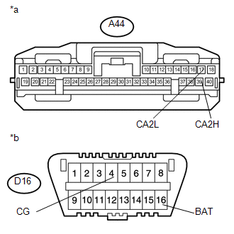
*a |
Front view of wire harness connector (to Driving Support ECU Assembly) |
|
*b |
Front view of DLC3 |
(a) Disconnect the driving support ECU assembly connector.
(b) Measure the resistance according to the value(s) in the table below.
Standard Resistance:
|
Tester Connection |
Switch Condition |
Specified Condition |
|---|---|---|
|
A44-39 (CA2H) - A44-17 (CA2L) |
Ignition switch off |
54 to 69 Ω |
|
A44-39 (CA2H) - D16-4 (CG) |
Ignition switch off |
200 Ω or higher |
|
A44-17 (CA2L) - D16-4 (CG) |
Ignition switch off |
200 Ω or higher |
|
A44-39 (CA2H) - D16-16 (BAT) |
Ignition switch off |
6 kΩ or higher |
|
A44-17 (CA2L) - D16-16 (BAT) |
Ignition switch off |
6 kΩ or higher |
| OK |
|
| NG |
|
REPAIR OR REPLACE CAN BRANCH WIRE CONNECTED TO DRIVING SUPPORT ECU ASSEMBLY (CAN-H, CAN-L) |
|
42. |
CONNECT CONNECTOR |
(a) Reconnect the D182 No. 4 junction connector connector.
|
|
43. |
CHECK FOR SHORT IN CAN BUS WIRES (AFS ECU (HEADLIGHT SWIVEL ECU ASSEMBLY)) |
|
*a |
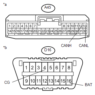
Front view of wire harness connector (to AFS ECU (Headlight Swivel ECU Assembly)) |
|
*b |
Front view of DLC3 |
(a) Disconnect the AFS ECU (headlight swivel ECU assembly) connector.
(b) Measure the resistance according to the value(s) in the table below.
Standard Resistance:
|
Tester Connection |
Switch Condition |
Specified Condition |
|---|---|---|
|
A45-12 (CANH) - A45-13 (CANL) |
Ignition switch off |
54 to 69 Ω |
|
A45-12 (CANH) - D16-4 (CG) |
Ignition switch off |
200 Ω or higher |
|
A45-13 (CANL) - D16-4 (CG) |
Ignition switch off |
200 Ω or higher |
|
A45-12 (CANH) - D16-16 (BAT) |
Ignition switch off |
6 kΩ or higher |
|
A45-13 (CANL) - D16-16 (BAT) |
Ignition switch off |
6 kΩ or higher |
| OK |
|
| NG |
|
REPAIR OR REPLACE CAN BRANCH WIRE CONNECTED TO AFS ECU (HEADLIGHT SWIVEL ECU ASSEMBLY) (CAN-H, CAN-L) |
|
44. |
CONNECT CONNECTOR |
(a) Reconnect the D182 No. 4 junction connector connector.
|
|
45. |
CHECK FOR SHORT IN CAN BUS WIRES (PARKING ASSIST ECU) |
|
*a |
Front view of wire harness connector (to Parking Assist ECU) |
|
*b |
Front view of DLC3 |
(a) Disconnect the parking assist ECU connector.
(b) Measure the resistance according to the value(s) in the table below.
Standard Resistance:
|
Tester Connection |
Switch Condition |
Specified Condition |
|---|---|---|
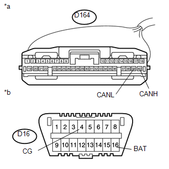
|
D164-40 (CANH) - D164-39 (CANL) |
Ignition switch off |
54 to 69 Ω |
|
D164-40 (CANH) - D16-4 (CG) |
Ignition switch off |
200 Ω or higher |
|
D164-39 (CANL) - D16-4 (CG) |
Ignition switch off |
200 Ω or higher |
|
D164-40 (CANH) - D16-16 (BAT) |
Ignition switch off |
6 kΩ or higher |
|
D164-39 (CANL) - D16-16 (BAT) |
Ignition switch off |
6 kΩ or higher |
| OK |
|
| NG |
|
REPAIR OR REPLACE CAN BRANCH WIRE CONNECTED TO PARKING ASSIST ECU (CAN-H, CAN-L) |
|
46. |
CONNECT CONNECTOR |
(a) Reconnect the L55 No. 5 junction connector connector.
|
|
47. |
CHECK FOR SHORT IN CAN BUS WIRES (BLIND SPOT MONITOR SENSOR RH) |
|
*a |
Front view of wire harness connector (to Blind Spot Monitor Sensor RH) |
|
*b |
Front view of DLC3 |
(a) Disconnect the blind spot monitor sensor RH connector.
(b) Measure the resistance according to the value(s) in the table below.
Standard Resistance:
|
Tester Connection |
Switch Condition |
Specified Condition |
|---|---|---|
|
q2-2 (CA1P) - q2-7 (CA1N) |
Ignition switch off |
54 to 69 Ω |
|
q2-2 (CA1P) - D16-4 (CG) |
Ignition switch off |
200 Ω or higher |
|
q2-7 (CA1N) - D16-4 (CG) |
Ignition switch off |
200 Ω or higher |
|
q2-2 (CA1P) - D16-16 (BAT) |
Ignition switch off |
6 kΩ or higher |
|
q2-7 (CA1N) - D16-16 (BAT) |
Ignition switch off |
6 kΩ or higher |
| OK |
|
| NG |
|
REPAIR OR REPLACE CAN BRANCH WIRE CONNECTED TO BLIND SPOT MONITOR SENSOR RH (CAN-H, CAN-L) |
|
48. |
CHECK HARNESS AND CONNECTOR (POWER MANAGEMENT CONTROL ECU - POWER SOURCE) |
|
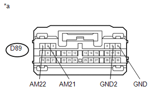
*a |
Front view of wire harness connector (to Power Management Control ECU) |
(a) Connect the cable to the negative (-) battery terminal.
NOTICE:
When disconnecting the cable, some systems need to be initialized after the cable is reconnected (See page
).
(b) Disconnect the power management control ECU.
(c) Measure the resistance according to the value(s) in the table below.
Standard Resistance:
|
Tester Connection |
Condition |
Specified Condition |
|---|---|---|
|
D89-6 (GND) - Body ground |
Always |
Below 1 Ω |
|
D89-5 (GND2) - Body ground |
Always |
Below 1 Ω |
(d) Measure the voltage according to the value(s) in the table below.
Standard Voltage:
|
Tester Connection |
Condition |
Specified Condition |
|---|---|---|
|
D89-2 (AM21) - Body ground |
Always |
11 to 14 V |
|
D89-1 (AM22) - Body ground |
Always |
11 to 14 V |
| OK |
|
| NG |
|
REPAIR OR REPLACE HARNESS OR CONNECTOR |
|
49. |
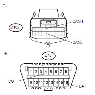
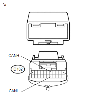
CHECK CAN BUS WIRE (MAIN WIRE FOR DISCONNECTION, BUS LINE FOR SHORT CIRCUIT) |
|
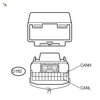
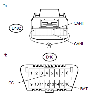
*a |
Junction connector with harness connected (No. 4 Junction Connector) |
|
*b |
Front view of DLC3 |
(a) Measure the resistance according to the value(s) in the table below.
Standard Resistance:
|
Tester Connection |
Switch Condition |
Specified Condition |
Resistance Malfunction |
|---|---|---|---|
|
D182-5 (CANH) - D182-16 (CANL) |
Ignition switch off |
54 to 69 Ω |
Below 53 Ω: Short in line |
|
Ignition switch off |
70 Ω or higher: Open in CAN main bus line |
||
|
D182-5 (CANH) - D16-16 (BAT) |
Ignition switch off |
6 kΩ or higher |
Below 6 kΩ: +B short |
|
D182-16 (CANL) - D16-16 (BAT) |
Ignition switch off |
6 kΩ or higher |
Below 6 kΩ: +B short |
|
D182-5 (CANH) - D16-4 (CG) |
Ignition switch off |
200 Ω or higher |
Below 200 Ω: Ground short |
|
D182-16 (CANL) - D16-4 (CG) |
Ignition switch off |
200 Ω or higher |
Below 200 Ω: Ground short |
Result
|
Result |
Proceed to |
|---|---|
|
NG - Open in CAN main wire |
A |
|
NG - Short in line - +B short - Ground short |
B |
|
OK |
C |
| B |
|
| C |
|
|
|
50. |
CHECK FOR OPEN IN CAN BUS MAIN WIRE (NO. 4 JUNCTION CONNECTOR - NETWORK GATEWAY ECU) |
|
(a) Disconnect the No. 4 junction connector connector. |
|
(b) Measure the resistance according to the value(s) in the table below.
Standard Resistance:
|
Tester Connection |
Switch Condition |
Specified Condition |
|---|---|---|
|
D182-5 (CANH) - D182-16 (CANL) |
Ignition switch off |
108 to 132 Ω |
Result
|
Result |
Proceed to |
|---|---|
|
NG |
A |
|
OK |
B |
| B |
|
|
|
51. |
CONNECT CONNECTOR |
(a) Reconnect the D182 No. 4 junction connector connector.
|
|
52. |
CHECK OPEN IN CAN BUS MAIN WIRE (NETWORKGATEWAYECU - NO. 4 JUNCTION CONNECTOR) |
|
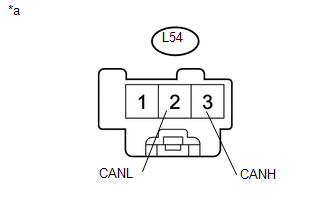
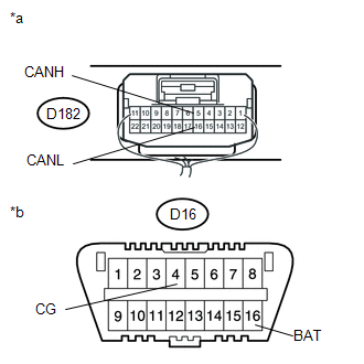
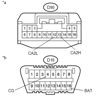
*a |
Rear view of wire harness connector (to Network Gateway ECU) |
(a) Disconnect the network gateway ECU connector.
(b) Measure the resistance according to the value(s) in the table below.
Standard Resistance:
|
Tester Connection |
Switch Condition |
Specified Condition |
|---|---|---|
|
D89-12 (CA3P) - D89-11 (CA3N) |
Ignition switch off |
108 to 132 Ω |
| OK |
|
| NG |
|
REPAIR OR REPLACE CAN MAIN WIRE CONNECTED TO NETWORK GATEWAY ECU (NETWORK GATEWAY ECU - NO. 4 JUNCTIONCONNECTOR) |
|
53. |
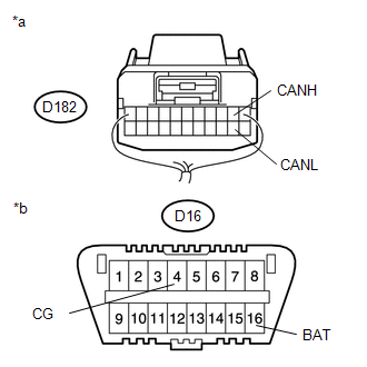
CHECK FOR OPEN IN CAN BUS MAIN WIRE (NO. 4 JUNCTION CONNECTOR - NO. 5 JUNCTION CONNECTOR) |
|
(a) Disconnect the No. 4 junction connector connector. |
|
(b) Measure the resistance according to the value(s) in the table below.
Standard Resistance:
|
Tester Connection |
Switch Condition |
Specified Condition |
|---|---|---|
|
D182-2 (CANH) - D182-13 (CANL) |
Ignition switch off |
108 to 132 Ω |
Result
|
Result |
Proceed to |
|---|---|
|
NG |
A |
|
OK |
B |
| B |
|
REPAIR NO. 4 JUNCTION CONNECTOR |
|
|
54. |
CONNECT CONNECTOR |
(a) Reconnect the D182 No. 4 junction connector connector.
|
|
55. |
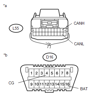
CHECK FOR OPEN IN CAN BUS MAIN WIRE (NO. 4 JUNCTION CONNECTOR - NO. 5 JUNCTION CONNECTOR) |
|
(a) Disconnect the No. 5 junction connector connector. |
|
(b) Measure the resistance according to the value(s) in the table below.
Standard Resistance:
|
Tester Connection |
Switch Condition |
Specified Condition |
|---|---|---|
|
L55-2 (CANH) - L55-13 (CANL) |
Ignition switch off |
108 to 132 Ω |
| NG |
|
REPAIR OR REPLACE CAN MAIN WIRE OR CONNECTOR (NO. 4 JUNCTION CONNECTOR - NO. 5 JUNCTION CONNECTOR) |
|
|
56. |
CHECK FOR OPEN IN CAN BUS MAIN WIRE (NO. 5 JUNCTION CONNECTOR SIDE) |
|
(a) Measure the resistance according to the value(s) in the table below. Standard Resistance:
|
|
| NG |
|
REPLACE NO. 5 JUNCTION CONNECTOR |
|
|
57. |
CONNECT CONNECTOR |
(a) Reconnect the L55 No. 5 junction connector connector.
|
|
58. |
CHECK FOR OPEN IN CAN BUS MAIN WIRE (NO. 2 JUNCTION TERMINAL - NO. 5 JUNCTION CONNECTOR) |
(a) Disconnect the No. 2 junction terminal connector.
|
(b) Measure the resistance according to the value(s) in the table below. Standard Resistance:
|
|
| OK |
|
REPLACE NO. 2 JUNCTION TERMINAL |
| NG |
|
REPAIR OR REPLACE CAN MAIN WIRE OR CONNECTOR (NO. 2 JUNCTION TERMINAL - NO. 5 JUNCTION CONNECTOR) |
|
59. |
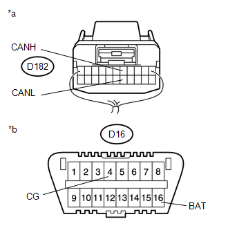
CHECK FOR SHORT IN CAN BUS WIRES (NO. 4 JUNCTION CONNECTOR - NETWORK GATEWAY ECU) |
|
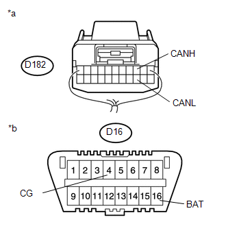
*a |
Rear view of wire harness connector (to No. 4 Junction Connector) |
|
*b |
Front view of DLC3 |
(a) Disconnect the No. 4 junction connector connector.
(b) Measure the resistance according to the value(s) in the table below.
Standard Resistance:
|
Tester Connection |
Switch Condition |
Specified Condition |
|---|---|---|
|
D182-5 (CANH) - D182-16 (CANL) |
Ignition switch off |
108 to 132 Ω |
|
D182-5 (CANH) - D16-4 (CG) |
Ignition switch off |
200 Ω or higher |
|
D182-16 (CANL) - D16-4 (CG) |
Ignition switch off |
200 Ω or higher |
|
D182-5 (CANH) - D16-16 (BAT) |
Ignition switch off |
6 kΩ or higher |
|
D182-16 (CANL) - D16-16 (BAT) |
Ignition switch off |
6 kΩ or higher |
| NG |
|
|
|
60. |
CHECK FOR SHORT IN CAN BUS WIRES (NO. 4 JUNCTION CONNECTOR - CLEARANCE WARNING ECU ASSEMBLY) |
HINT:
For vehicle without intuitive parking assist system, go to step 61.
|
*a |
Rear view of wire harness connector (to No. 4 Junction Connector) |
|
*b |
Front view of DLC3 |
(a) Measure the resistance according to the value(s) in the table below.
Standard Resistance:
|
Tester Connection |
Switch Condition |
Specified Condition |
|---|---|---|
|
D182-1 (CANH) - D182-12 (CANL) |
Ignition switch off |
200 Ω or higher |
|
D182-1 (CANH) - D16-4 (CG) |
Ignition switch off |
200 Ω or higher |
|
D182-12 (CANL) - D16-4 (CG) |
Ignition switch off |
200 Ω or higher |
|
D182-1 (CANH) - D16-16 (BAT) |
Ignition switch off |
6 kΩ or higher |
|
D182-12 (CANL) - D16-16 (BAT) |
Ignition switch off |
6 kΩ or higher |
| NG |
|
|
|
61. |
CHECK FOR SHORT IN CAN BUS WIRES (NO. 4 JUNCTION CONNECTOR - SEAT BELT CONTROL ECU) |
|
*a |
Rear view of wire harness connector (to No. 4 Junction Connector) |
|
*b |
Front view of DLC3 |
HINT:
For vehicle without pre-collision system, go to step 62.
(a) Measure the resistance according to the value(s) in the table below.
Standard Resistance:
|
Tester Connection |
Switch Condition |
Specified Condition |
|---|---|---|
|
D182-3 (CANH) - D182-14 (CANL) |
Ignition switch off |
200 Ω or higher |
|
D182-3 (CANH) - D16-4 (CG) |
Ignition switch off |
200 Ω or higher |
|
D182-14 (CANL) - D16-4 (CG) |
Ignition switch off |
200 Ω or higher |
|
D182-3 (CANH) - D16-16 (BAT) |
Ignition switch off |
6 kΩ or higher |
|
D182-14 (CANL) - D16-16 (BAT) |
Ignition switch off |
6 kΩ or higher |
| NG |
|
|
|
62. |
CHECK FOR SHORT IN CAN BUS WIRES (NO. 4 JUNCTION CONNECTOR - DRIVING SUPPORT ECU ASSEMBLY) |
|
*a |
Rear view of wire harness connector (to No. 4 Junction Connector) |
|
*b |
Front view of DLC3 |
HINT:
For vehicle without dynamic radar cruise control system, go to step 63.
(a) Measure the resistance according to the value(s) in the table below.
Standard Resistance:
|
Tester Connection |
Switch Condition |
Specified Condition |
|---|---|---|
|
D182-4 (CANH) - D182-15 (CANL) |
Ignition switch off |
200 Ω or higher |
|
D182-4 (CANH) - D16-4 (CG) |
Ignition switch off |
200 Ω or higher |
|
D182-15 (CANL) - D16-4 (CG) |
Ignition switch off |
200 Ω or higher |
|
D182-4 (CANH) - D16-16 (BAT) |
Ignition switch off |
6 kΩ or higher |
|
D182-15 (CANL) - D16-16 (BAT) |
Ignition switch off |
6 kΩ or higher |
| NG |
|
|
|
63. |
CHECK FOR SHORT IN CAN BUS WIRES (NO. 4 JUNCTION CONNECTOR - AFS ECU (HEADLIGHT SWIVEL ECU ASSEMBLY)) |
|
*a |
Rear view of wire harness connector (to No. 4 Junction Connector) |
|
*b |
Front view of DLC3 |
HINT:
For vehicle without HID headlight system, go to step 64.
(a) Measure the resistance according to the value(s) in the table below.
Standard Resistance:
|
Tester Connection |
Switch Condition |
Specified Condition |
|---|---|---|
|
D182-6 (CANH) - D182-17 (CANL) |
Ignition switch off |
200 Ω or higher |
|
D182-6 (CANH) - D16-4 (CG) |
Ignition switch off |
200 Ω or higher |
|
D182-17 (CANL) - D16-4 (CG) |
Ignition switch off |
200 Ω or higher |
|
D182-6 (CANH) - D16-16 (BAT) |
Ignition switch off |
6 kΩ or higher |
|
D182-17 (CANL) - D16-16 (BAT) |
Ignition switch off |
6 kΩ or higher |
| NG |
|
|
|
64. |
CHECK FOR SHORT IN CAN BUS WIRES (NO. 4 JUNCTION CONNECTOR - PARKING ASSIST ECU) |
|
*a |
Rear view of wire harness connector (to No. 4 Junction Connector) |
|
*b |
Front view of DLC3 |
HINT:
For vehicle without parking assist monitor system, go to step 65.
(a) Measure the resistance according to the value(s) in the table below.
Standard Resistance:
|
Tester Connection |
Switch Condition |
Specified Condition |
|---|---|---|
|
D182-7 (CANH) - D182-18 (CANL) |
Ignition switch off |
200 Ω or higher |
|
D182-7 (CANH) - D16-4 (CG) |
Ignition switch off |
200 Ω or higher |
|
D182-18 (CANL) - D16-4 (CG) |
Ignition switch off |
200 Ω or higher |
|
D182-7 (CANH) - D16-16 (BAT) |
Ignition switch off |
6 kΩ or higher |
|
D182-18 (CANL) - D16-16 (BAT) |
Ignition switch off |
6 kΩ or higher |
| NG |
|
|
|
65. |
CHECK FOR SHORT IN CAN BUS WIRES (NO. 4 JUNCTION CONNECTOR SIDE) |
|
(a) Measure the resistance according to the value(s) in the table below. Standard Resistance:
Result
|
|
| B |
|
REPLACE JUNCTION CONNECTOR |
|
|
66. |
CONNECT CONNECTOR |
(a) Reconnect the D182 No. 4 junction connector connector.
|
|
67. |
CHECK FOR SHORT IN CAN BUS WIRES (NO. 5 JUNCTION CONNECTOR - NO. 4 JUNCTION CONNECTOR) |
|
(a) Disconnect the No. 5 junction connector connector. |
|
(b) Measure the resistance according to the value(s) in the table below.
Standard Resistance:
|
Tester Connection |
Switch Condition |
Specified Condition |
|---|---|---|
|
L55-2 (CANH) - L55-13 (CANL) |
Ignition switch off |
108 to 132 Ω |
|
L55-2 (CANH) - D16-4 (CG) |
Ignition switch off |
200 Ω or higher |
|
L55-13 (CANL) - D16-4 (CG) |
Ignition switch off |
200 Ω or higher |
|
L55-2 (CANH) - D16-16 (BAT) |
Ignition switch off |
6 kΩ or higher |
|
L55-13 (CANL) - D16-16 (BAT) |
Ignition switch off |
6 kΩ or higher |
| NG |
|
REPAIR OR REPLACE CAN MAIN WIRE OR CONNECTOR (NO. 5 JUNCTION CONNECTOR - NO. 4 JUNCTION CONNECTOR) |
|
|
68. |
CHECK FOR SHORT IN CAN BUS WIRES (NO. 5 JUNCTION CONNECTOR - BLIND SPOT MONITOR SENSOR RH) |
HINT:
For vehicle without blind spot monitor system, go to 69.
|
(a) Measure the resistance according to the value(s) in the table below. Standard Resistance:
|
|
| NG |
|
|
|
69. |
CHECK FOR SHORT IN CAN BUS WIRES (NO. 5 JUNCTION CONNECTOR SIDE) |
|
(a) Measure the resistance according to the value(s) in the table below. Standard Resistance:
|
|
| NG |
|
REPLACE NO. 5 JUNCTION CONNECTOR |
|
|
70. |
CONNECT CONNECTOR |
(a) Reconnect the L55 No. 5 junction connector connector.
|
|
71. |
CHECK FOR SHORT IN CAN BUS WIRES (NO. 2 JUNCTION TERMINAL - NO. 5 JUNCTION CONNECTOR) |
(a) Disconnect the No. 2 junction terminal connector.
|
(b) Measure the resistance according to the value(s) in the table below. Standard Resistance:
|
|
| OK |
|
REPLACE NO. 2 JUNCTION TERMINAL |
| NG |
|
REPAIR OR REPLACE CAN MAIN WIRE OR CONNECTOR (NO. 2 JUNCTION TERMINAL - NO. 5 JUNCTION CONNECTOR) |
|
72. |
CONNECT CONNECTOR |
(a) Reconnect the D182 No. 4 junction connector connector.
|
|
73. |
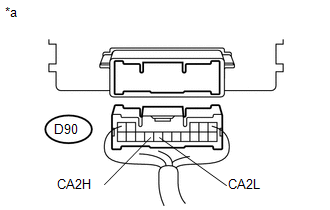
CHECK FOR SHORT IN CAN BUS WIRES (NETWORK GATEWAY ECU) |
|
*a |
Front view of wire harness connector (to Network Gateway ECU) |
|
*b |
Front view of DLC3 |
(a) Disconnect the network gateway ECU connector.
(b) Measure the resistance according to the value(s) in the table below.
Standard Resistance:
|
Tester Connection |
Switch Condition |
Specified Condition |
|---|---|---|
|
D90-13 (CA2H) - D90-12 (CA2L) |
Ignition switch off |
108 to 132 Ω |
|
D90-13 (CA2H) - D16-4 (CG) |
Ignition switch off |
200 Ω or higher |
|
D90-12 (CA2L) - D16-4 (CG) |
Ignition switch off |
200 Ω or higher |
|
D90-13 (CA2H) - D16-16 (BAT) |
Ignition switch off |
6 kΩ or higher |
|
D90-12 (CA2L) - D16-16 (BAT) |
Ignition switch off |
6 kΩ or higher |
| OK |
|
| NG |
|
REPAIR OR REPLACE CAN MAIN WIRE CONNECTED TO NETWORK GATEWAY ECU (CAN-H, CAN-L) |
|
74. |
CONNECT CONNECTOR |
(a) Reconnect the D182 No. 4 junction connector connector.
|
|
75. |
CHECK FOR SHORT IN CAN BUS WIRES (CLEARANCE WARNING ECU ASSEMBLY) |
|
*a |
Front view of wire harness connector (to Clearance Warning ECU Assembly) |
|
*b |
Front view of DLC3 |
(a) Disconnect the clearance warning ECU assembly connector.
(b) Measure the resistance according to the value(s) in the table below.
Standard Resistance:
|
Tester Connection |
Switch Condition |
Specified Condition |
|---|---|---|
|
D77-3 (R1) - D77-5 (R2) |
Ignition switch off |
54 to 69 Ω |
|
D77-3 (R1) - D16-4 (CG) |
Ignition switch off |
200 Ω or higher |
|
D77-5 (R2) - D16-4 (CG) |
Ignition switch off |
200 Ω or higher |
|
D77-3 (R1) - D16-16 (BAT) |
Ignition switch off |
6 kΩ or higher |
|
D77-5 (R2) - D16-16 (BAT) |
Ignition switch off |
6 kΩ or higher |
| OK |
|
| NG |
|
REPAIR OR REPLACE CAN BRANCH WIRE CONNECTED TO CLEARANCE WARNING ECU ASSEMBLY (CAN-H, CAN-L) |
|
76. |
CONNECT CONNECTOR |
(a) Reconnect the D182 No. 4 junction connector connector.
|
|
77. |
CHECK FOR SHORT IN CAN BUS WIRES (SEAT BELT CONTROL ECU) |
|
*a |
Front view of wire harness connector (to Seat Belt Control ECU) |
|
*b |
Front view of DLC3 |
(a) Disconnect the seat belt control ECU connector.
(b) Measure the resistance according to the value(s) in the table below.
Standard Resistance:
|
Tester Connection |
Switch Condition |
Specified Condition |
|---|---|---|
|
D83-1 (CANH) - D83-2 (CANL) |
Ignition switch off |
54 to 69 Ω |
|
D83-1 (CANH) - D16-4 (CG) |
Ignition switch off |
200 Ω or higher |
|
D83-2 (CANL) - D16-4 (CG) |
Ignition switch off |
200 Ω or higher |
|
D83-1 (CANH) - D16-16 (BAT) |
Ignition switch off |
6 kΩ or higher |
|
D83-2 (CANL) - D16-16 (BAT) |
Ignition switch off |
6 kΩ or higher |
| OK |
|
| NG |
|
REPAIR OR REPLACE CAN BRANCH WIRE CONNECTED TO DRIVING SUPPORT ECU ASSEMBLY (CAN-H, CAN-L) |
|
78. |
CONNECT CONNECTOR |
(a) Reconnect the D182 No. 4 junction connector connector.
|
|
79. |
CHECK FOR SHORT IN CAN BUS WIRES (DRIVING SUPPORT ECU ASSEMBLY) |
|
*a |
Front view of wire harness connector (to Driving Support ECU Assembly) |
|
*b |
Front view of DLC3 |
(a) Disconnect the driving support ECU assembly connector.
(b) Measure the resistance according to the value(s) in the table below.
Standard Resistance:
|
Tester Connection |
Switch Condition |
Specified Condition |
|---|---|---|
|
A44-39 (CA2H) - A44-17 (CA2L) |
Ignition switch off |
54 to 69 Ω |
|
A44-39 (CA2H) - D16-4 (CG) |
Ignition switch off |
200 Ω or higher |
|
A44-17 (CA2L) - D16-4 (CG) |
Ignition switch off |
200 Ω or higher |
|
A44-39 (CA2H) - D16-16 (BAT) |
Ignition switch off |
6 kΩ or higher |
|
A44-17 (CA2L) - D16-16 (BAT) |
Ignition switch off |
6 kΩ or higher |
| OK |
|
| NG |
|
REPAIR OR REPLACE CAN BRANCH WIRE CONNECTED TO DRIVING SUPPORT ECU ASSEMBLY (CAN-H, CAN-L) |
|
80. |
CONNECT CONNECTOR |
(a) Reconnect the D182 No. 4 junction connector connector.
|
|
81. |
CHECK FOR SHORT IN CAN BUS WIRES (AFS ECU (HEADLIGHT SWIVEL ECU ASSEMBLY)) |
|
*a |
Front view of wire harness connector (to AFS ECU (Headlight Swivel ECU Assembly)) |
|
*b |
Front view of DLC3 |
(a) Disconnect the AFS ECU (headlight swivel ECU assembly) connector.
(b) Measure the resistance according to the value(s) in the table below.
Standard Resistance:
|
Tester Connection |
Switch Condition |
Specified Condition |
|---|---|---|
|
A45-12 (CANH) - A45-13 (CANL) |
Ignition switch off |
54 to 69 Ω |
|
A45-12 (CANH) - D16-4 (CG) |
Ignition switch off |
200 Ω or higher |
|
A45-13 (CANL) - D16-4 (CG) |
Ignition switch off |
200 Ω or higher |
|
A45-12 (CANH) - D16-16 (BAT) |
Ignition switch off |
6 kΩ or higher |
|
A45-13 (CANL) - D16-16 (BAT) |
Ignition switch off |
6 kΩ or higher |
| OK |
|
| NG |
|
REPAIR OR REPLACE CAN BRANCH WIRE CONNECTED TO AFS ECU (HEADLIGHT SWIVEL ECU ASSEMBLY) (CAN-H, CAN-L) |
|
82. |
CONNECT CONNECTOR |
(a) Reconnect the D182 No. 4 junction connector connector.
|
|
83. |
CHECK FOR SHORT IN CAN BUS WIRES (PARKING ASSIST ECU) |
|
*a |
Front view of wire harness connector (to Parking Assist ECU) |
|
*b |
Front view of DLC3 |
(a) Disconnect the parking assist ECU connector.
(b) Measure the resistance according to the value(s) in the table below.
Standard Resistance:
|
Tester Connection |
Switch Condition |
Specified Condition |
|---|---|---|
|
D164-40 (CANH) - D164-39 (CANL) |
Ignition switch off |
54 to 69 Ω |
|
D164-40 (CANH) - D16-4 (CG) |
Ignition switch off |
200 Ω or higher |
|
D164-39 (CANL) - D16-4 (CG) |
Ignition switch off |
200 Ω or higher |
|
D164-40 (CANH) - D16-16 (BAT) |
Ignition switch off |
6 kΩ or higher |
|
D164-39 (CANL) - D16-16 (BAT) |
Ignition switch off |
6 kΩ or higher |
| OK |
|
REPLACE PARKING ASSIST ECU |
| NG |
|
REPAIR OR REPLACE CAN BRANCH WIRE CONNECTED TO PARKING ASSIST ECU (CAN-H, CAN-L) |
|
84. |
CONNECT CONNECTOR |
(a) Reconnect the L55 No. 5 junction connector connector.
|
|
85. |
CHECK FOR SHORT IN CAN BUS WIRES (BLIND SPOT MONITOR SENSOR RH) |
|
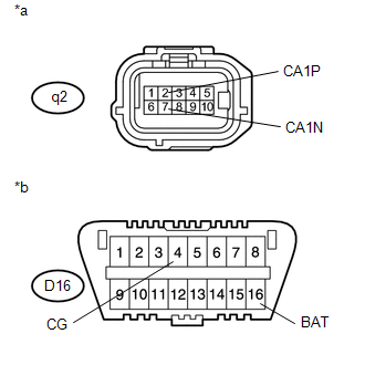
*a |
Front view of wire harness connector (to Blind Spot Monitor Sensor RH) |
|
*b |
Front view of DLC3 |
(a) Disconnect the blind spot monitor sensor RH connector.
(b) Measure the resistance according to the value(s) in the table below.
Standard Resistance:
|
Tester Connection |
Switch Condition |
Specified Condition |
|---|---|---|
|
q2-2 (CA1P) - q2-7 (CA1N) |
Ignition switch off |
54 to 69 Ω |
|
q2-2 (CA1P) - D16-4 (CG) |
Ignition switch off |
200 Ω or higher |
|
q2-7 (CA1N) - D16-4 (CG) |
Ignition switch off |
200 Ω or higher |
|
q2-2 (CA1P) - D16-16 (BAT) |
Ignition switch off |
6 kΩ or higher |
|
q2-7 (CA1N) - D16-16 (BAT) |
Ignition switch off |
6 kΩ or higher |
| OK |
|
REPLACE BLIND SPOT MONITOR SENSOR RH |
| NG |
|
REPAIR OR REPLACE CAN BRANCH WIRE CONNECTED TO BLIND SPOT MONITOR SENSOR RH (CAN-H, CAN-L) |
|
86. |
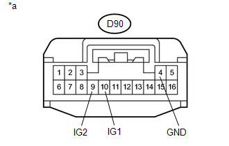
CHECK HARNESS AND CONNECTOR (NETWORK GATEWAY ECU - POWER SOURCE) |
|
*a |
Front view of wire harness connector (to Network Gateway ECU) |
(a) Connect the cable to the negative (-) battery terminal.
NOTICE:
When disconnecting the cable, some systems need to be initialized after the cable is reconnected (See page
).
(b) Disconnect the network gateway ECU connector.
(c) Measure the resistance according to the value(s) in the table below.
Standard Resistance:
|
Tester Connection |
Condition |
Specified Condition |
|---|---|---|
|
D90-4 (GND) - Body ground |
Always |
Below 1 Ω |
(d) Measure the voltage according to the value(s) in the table below.
Standard Voltage:
|
Tester Connection |
Switch Condition |
Specified Condition |
|---|---|---|
|
D90-9 (IG2) - Body ground |
Ignition switch ON |
11 to 14 V |
|
D90-10 (IG1) - Body ground |
Ignition switch ON |
11 to 14 V |
| OK |
|
REPLACE NETWORK GATEWAY ECU |
| NG |
|
REPAIR OR REPLACE HARNESS OR CONNECTOR |
|
|
|