| Last Modified: 08-28-2024 | 6.11:8.1.0 | Doc ID: RM100000000YXOV |
| Model Year Start: 2017 | Model: Sienna | Prod Date Range: [08/2016 - ] |
| Title: 2GR-FKS (FUEL): FUEL TANK: REMOVAL; 2017 - 2020 MY Sienna [08/2016 - ] | ||
REMOVAL
PROCEDURE
1. DISCHARGE FUEL SYSTEM PRESSURE
Click here
![2017 - 2020 MY Sienna [08/2016 - ]; 2GR-FKS (FUEL): FUEL SYSTEM: PRECAUTION](/t3Portal/stylegraphics/info.gif)
2. REMOVE CHARCOAL CANISTER PROTECTOR
Click here
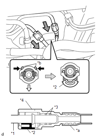
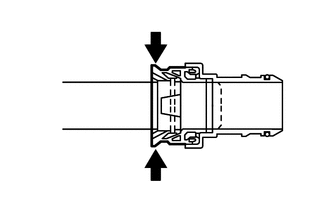
3. DISCONNECT FUEL TANK MAIN TUBE SUB-ASSEMBLY
NOTICE:
Remove any foreign matter on the fuel tube connector and fuel pipe before performing this work.
(a) Disconnect the fuel tank main tube sub-assembly from the fuel pipe.
|
*1 |
Fuel Pipe |
|
*2 |
Retainer |
|
*3 |
O-ring |
|
*4 |
Fuel Tube Connector |
|
*a |
Nylon Tube |
|
*b |
Claw |

|
Push |

|
Pull out |

|
Pull off |
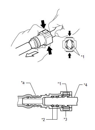
(1) Disengage the 2 claws of the retainer. Pull out the retainer and disconnect the fuel tube connector from the fuel pipe.
NOTICE:
Be sure to disconnect the fuel tube connector by hand.
(2) If the fuel tube connector and fuel pipe are stuck, push and pull the fuel tube connector to release it. Pull the fuel tube connector off of the fuel pipe carefully.
NOTICE:
- Be sure to disconnect the fuel tube connector by hand.
- Do not scratch or allow any foreign matter to get on the parts when disconnecting them as the fuel tube connector has O-rings that seal the pipe (fuel pipe).
- Do not bend, twist, pinch or kink the nylon tube.
(3) Check that there is no foreign matter on the sealing surfaces of the disconnected fuel lines. Clean them if necessary.
(4) Cover the disconnected fuel pipe and fuel tube connector with plastic bags to prevent damage and contamination.
4. DRAIN FUEL
Click here
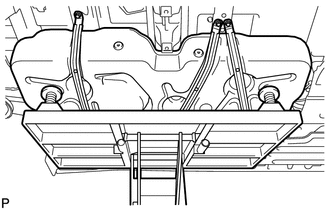
5. REMOVE CENTER EXHAUST PIPE ASSEMBLY (for 2WD)
|
(a) Remove the 4 bolts and 2 compression springs. |
|
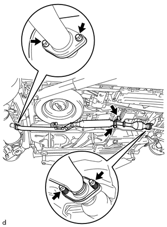
(b) Disconnect the 2 exhaust pipe supports and remove the center exhaust pipe assembly.
(c) Remove the 2 gaskets from the front exhaust pipe assembly and center exhaust pipe assembly.
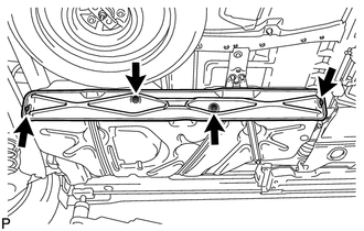
6. REMOVE NO. 1 FUEL TANK HEAT INSULATOR (for 2WD)
|
(a) Remove the 4 nuts and No. 1 fuel tank heat insulator. |
|
7. REMOVE PROPELLER WITH CENTER BEARING SHAFT ASSEMBLY (for AWD)
Click here
8. DISCONNECT FUEL TANK VENT HOSE
Click here
9. DISCONNECT CHARCOAL CANISTER OUTLET TUBE SUB-ASSEMBLY
Click here
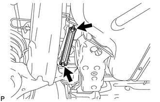
10. REMOVE REAR FLOOR NO. 2 CROSSMEMBER BRACE LH
|
(a) Remove the 2 bolts and the rear floor No. 2 crossmember brace LH. |
|
11. REMOVE FUEL TANK FILLER HOSE COVER
|
(a) Remove the 3 bolts and the fuel tank filler hose cover. |
|
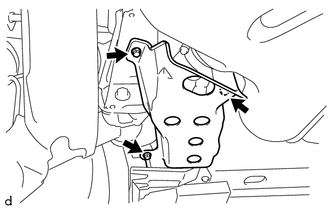
12. DISCONNECT FUEL TANK INLET PIPE SUB-ASSEMBLY
|
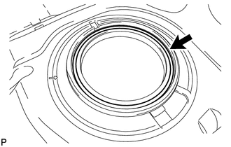
(a) Pry up the retainer of quick connector and disconnect the fuel tank inlet pipe sub-assembly from the fuel tank assembly. NOTICE:
|
|
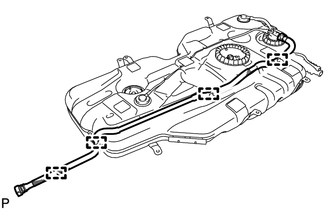
13. REMOVE FUEL TANK ASSEMBLY
(a) Disconnect the charcoal canister outlet tube sub-assembly.
Click here
|
|
Pinch |
NOTICE:
- Check for dirt or other foreign matter on the parts to be disconnected and clean them if necessary.
- The fuel tube connector seals with an O-ring. Ensure that there is no damage or foreign matter on the contact surface.
- Do not use any tools.
- Do not bend or twist the tubes.
- Protect the contact surface by covering it with a plastic bag.
- If the connector is stuck, push and pull on the parts to separate them.
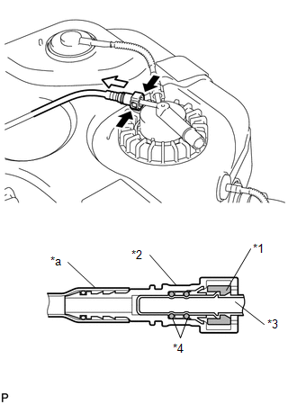
(b) Pinch the retainer to release it as shown in the illustration and disconnect the fuel tube.
Click here
|
*1 |
Retainer |
|
*2 |
O-ring |
|
*3 |
Fuel Tube Connector |
|
*4 |
Fuel Pipe |
|
*a |
Nylon Tube |
|
|
Pinch |
|
|
Pull Out |
NOTICE:
- Check for dirt or other foreign matter on the parts to be disconnected and clean them if necessary.
- The fuel tube connector seals with an O-ring. Ensure that there is no damage or foreign matter on the contact surface.
- Do not use any tools.
- Do not bend or twist the tubes.
- Protect the contact surface by covering it with a plastic bag.
- If the connector is stuck, push and pull on the parts to separate them.
|
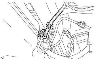
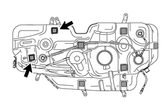
(c) Disengage the 2 wire harness clamps. |
|
|
(d) Using an engine lifter, support the fuel tank assembly. |
|
|
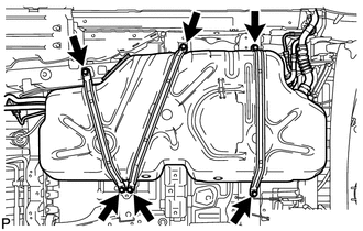
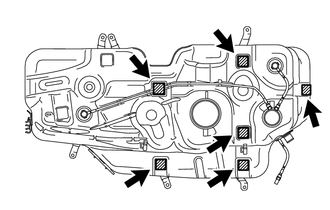
(e) Remove the 6 set bolts of the 3 fuel tank bands. |
|
|
(f) While operating the engine lifter, disengage the 4 guides for the wire harness and disconnect the 2 fuel pump connectors, then remove the fuel tank assembly and the 3 fuel tank bands from the vehicle. |
|
14. REMOVE FUEL TANK MAIN TUBE SUB-ASSEMBLY
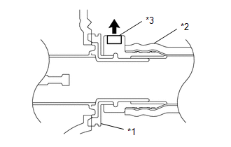
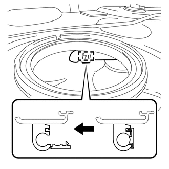
(a) Widen the tip of the tube joint clip and pull out the clip in the direction indicated by the arrow.
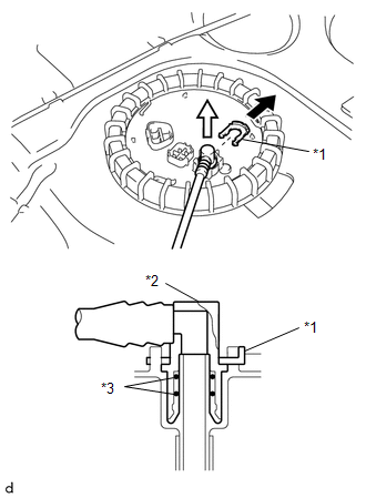
|
*1 |
Tube Joint Clip |
|
*2 |
Fuel Tube Connector |
|
*3 |
O-ring |
|
|
Pull Out |
|
|
Pull |
NOTICE:
- Check for dirt or other foreign matter on the parts to be disconnected and clean them if necessary.
- The fuel tube connector seals with an O-ring. Ensure that there is no damage or foreign matter on the contact surface.
- Do not use any tools.
- Do not bend or twist the tubes.
- Protect the contact surface by covering it with a plastic bag.
- If the connector is stuck, push and pull on the parts to separate them.
|
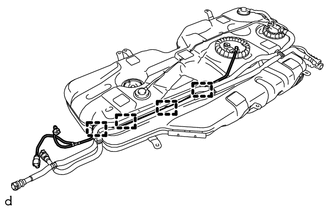
(b) Disengage the 4 guides and remove the fuel tank main tube sub-assembly. |
|
15. REMOVE CHARCOAL CANISTER OUTLET TUBE SUB-ASSEMBLY
|
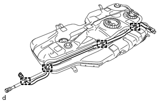
(a) Disengage the 4 clamps and remove the charcoal canister outlet tube sub-assembly. |
|
16. REMOVE FUEL TANK VENT HOSE
|
(a) Insert a screwdriver with its tip wrapped in protective tape into the quick connector cutout as shown in the illustration, pry up the retainer and disconnect the fuel tank vent hose. NOTICE:
|
|
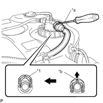
|
(b) Disengage the 4 clamps and remove the fuel tank vent hose and hose clamp. |
|
17. REMOVE FUEL PUMP GAUGE RETAINER
NOTICE:
Before performing these procedures, first cover the connectors and tube joints of the fuel suction tube with pump and gauge assembly with vinyl tape and then clean away any mud or other substances that may be adhering in order to prevent foreign matter from contaminating the fuel system.
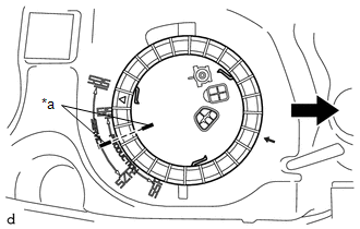
(a) Place paint marks on the fuel suction tube with pump and gauge assembly and vehicle body as shown in the illustration.
NOTICE:
- The fuel suction tube with pump and gauge assembly has 2 protrusions that engage with 2 notches on the fuel tank assembly to ensure correct alignment and to prevent the fuel suction tube with pump and gauge assembly from turning during installation and removal of the fuel pump gauge retainer.
- If the fuel pump gauge retainer is turned with the fuel suction tube with pump and gauge assembly misaligned, the fuel suction tube with pump and gauge assembly will turn with the fuel pump gauge retainer and may be damaged.
- The paint marks are used to ensure that the fuel suction tube with pump and gauge assembly does not turn with the fuel pump gauge retainer.
|
*a |
Paint Mark |
|
|
Front Side of Vehicle |
(b) Install SST to the fuel pump gauge retainer.
|
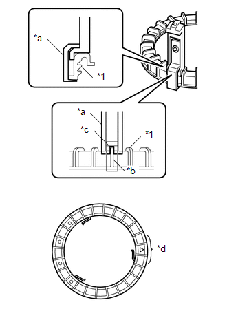
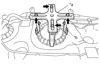
(1) Set 4 SST (claw set) to the fuel pump gauge retainer. SST: 09808-14031 09808-01080 09808-01090 09808-01100 NOTICE:
|
|
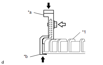
(2) Push SST (claw set) against the fuel pump gauge retainer and tighten SST (bolt).
|
*1 |
Fuel Pump Gauge Retainer |
|
*a |
SST (Claw Set) |
|
*b |
Hook |
|
|
Push |
|
|
SST (Bolt) |
(3) Temporarily install SST (plate) to SST (claw set) with 4 SST (bolt).
SST: 09808-14031
09808-01030
09808-01090
|
*a |
SST (Plate) |
|
*b |
SST (Claw Set) |
|
|
SST (Bolt) |
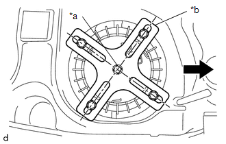
(4) Adjust the position of SST (claw set) so that the hole in SST (plate) for installing SST (handle) is in the center of the fuel pump gauge retainer.
|
*a |
Center Point of Fuel Pump Gauge Retainer |
|
*b |
SST (Plate) |
|
|
Front Side of Vehicle |
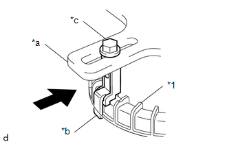
(5) Press SST (claw set) against the rib of the fuel pump gauge retainer and tighten SST (bolt).
|
*1 |
Fuel Pump Gauge Retainer |
|
*a |
SST (Plate) |
|
*b |
SST (Claw Set) |
|
*c |
SST (Bolt) |
|
|
Press |
(6) Install SST (handle) to SST (plate).
SST: 09808-14031
09808-01010
09808-01020
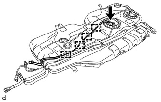
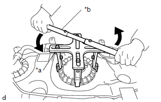
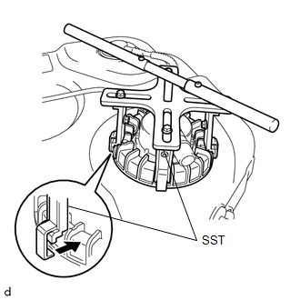
(c) Slowly loosen the fuel pump gauge retainer by approximately 90°.
|
*a |
SST (Plate) |
|
*b |
SST (Handle) |
|
|
Loosen |
NOTICE:
Do not spin SST too fast or use an impact wrench as this may result in damage to components.
(d) While one person loosens the fuel pump gauge retainer, have another person press down the rising fuel suction tube with pump and gauge assembly, securely insert the protrusion of the fuel suction tube with pump and gauge assembly into the groove of the fuel tank assembly, and then remove the fuel pump gauge retainer while making sure that the fuel suction tube with pump and gauge assembly is properly aligned.
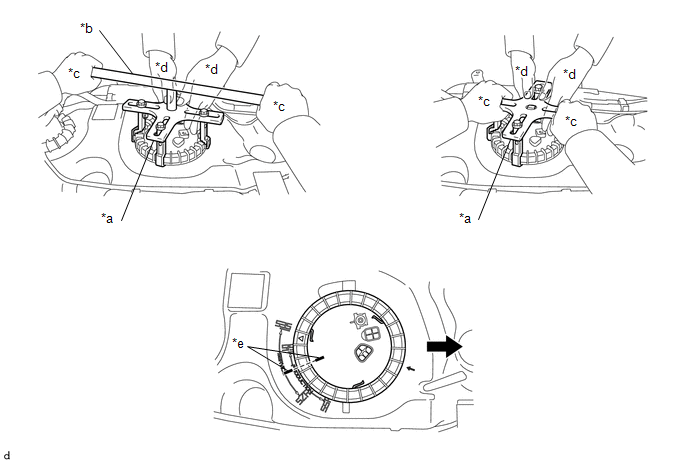
|
*a |
SST (Plate) |
*b |
SST (Handle) |
|
*c |
One Person in Charge of Loosening |
*d |
One Person in Charge of Pressing Down |
|
*e |
Paint Mark |
- |
- |
|
|
Front Side of Vehicle |
- |
- |
NOTICE:
- The fuel suction tube with pump and gauge assembly is pressed against the underside of the fuel tank assembly by a spring, and the constant upward pressure applied by this spring causes the fuel suction tube with pump and gauge assembly to rise up.
- If the fuel pump gauge retainer is turned while the fuel suction tube with pump and gauge assembly and fuel tank assembly are not correctly aligned, the fuel suction tube with pump and gauge assembly will move with the fuel pump gauge retainer, and the fuel suction tube with pump and gauge assembly and fuel tank assembly may both be damaged.
- Do not turn the fuel pump gauge retainer if the paint marks become misaligned.
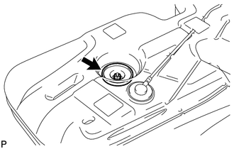
18. REMOVE FUEL SUCTION WITH PUMP AND GAUGE TUBE ASSEMBLY
(a) Remove the fuel suction with pump and gauge tube assembly from the fuel tank.
NOTICE:
Do not bend the arm of the sender gauge.
19. REMOVE FUEL SUCTION TUBE SET GASKET
|
(a) Remove the gasket from the fuel tank. |
|
20. REMOVE FUEL TANK OVERFILL CHECK VALVE ASSEMBLY
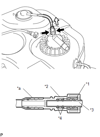
(a) Pinch the retainer to release it as shown in the illustration and disconnect the fuel tube.
Click here
|
*1 |
Retainer |
|
*2 |
Fuel Tube Connector |
|
*3 |
Fuel Pipe |
|
*4 |
O-ring |
|
*a |
Nylon Tube |
|
|
Pinch |
|
|
Pull Out |
NOTICE:
- Check for dirt or other foreign matter on the parts to be disconnected and clean them if necessary.
- The fuel tube connector seals with an O-ring. Ensure that there is no damage or foreign matter on the contact surface.
- Do not use any tools.
- Do not bend or twist the tubes.
- Protect the contact surface by covering it with a plastic bag.
- If the connector is stuck, push and pull on the parts to separate them.
(b) Pinch the retainer to release it as shown in the illustration and disconnect the fuel tube.
Click here
|
*1 |
Retainer |
|
*2 |
Fuel Tube Connector |
|
*3 |
Fuel Pipe |
|
*4 |
O-ring |
|
*a |
Nylon Tube |
|
|
Pinch |
|
|
Pull Out |
NOTICE:
- Check for dirt or other foreign matter on the parts to be disconnected and clean them if necessary.
- The fuel tube connector seals with an O-ring. Ensure that there is no damage or foreign matter on the contact surface.
- Do not use any tools.
- Do not bend or twist the tubes.
- Protect the contact surface by covering it with a plastic bag.
- If the connector is stuck, push and pull on the parts to separate them.
|
(c) Disengage the hose clamp. |
|
|
(d) Using SST, loosen the retainer. SST: 09808-14031 09808-01080 09808-01090 09808-01100 HINT: Align the ribs of the fuel pump gauge retainer with the tips of SST. NOTICE: Remove foreign matter around the fuel tank overfill check valve assembly before this operation. |
|
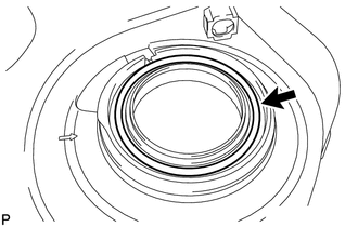
(e) Remove the fuel tank overfill check valve assembly.
21. REMOVE NO. 1 FUEL SUCTION TUBE SET GASKET
|
(a) Remove the gasket from the fuel tank. |
|
22. REMOVE FUEL TANK SIDE PLATE
|
(a) Remove the nut, bolt, fuel tank side plate and fuel tank bracket sub-assembly. |
|
23. REMOVE NO. 2 FUEL TANK CUSHION
|
(a) Remove the 2 No. 2 fuel tank cushions. |
|
24. REMOVE FUEL TANK CUSHION
|
(a) Remove the 6 fuel tank cushions. |
|
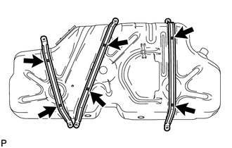
25. REMOVE FUEL TANK BAND
|
(a) Remove the 6 clips and 3 fuel tank bands. |
|
|
|
|