| Last Modified: 08-28-2024 | 6.11:8.1.0 | Doc ID: RM100000000YW9J |
| Model Year Start: 2017 | Model: Sienna | Prod Date Range: [08/2016 - ] |
| Title: 2GR-FKS (ENGINE MECHANICAL): CAMSHAFT: REMOVAL; 2017 - 2020 MY Sienna [08/2016 - ] | ||
REMOVAL
PROCEDURE
1. INSTALL ENGINE ASSEMBLY TO ENGINE STAND
Click here
![2017 - 2020 MY Sienna [08/2016 - ]; 2GR-FKS (ENGINE MECHANICAL): ENGINE ASSEMBLY: REMOVAL](/t3Portal/stylegraphics/info.gif)
2. REMOVE ENGINE HANGERS
Click here
3. REMOVE IGNITION COIL ASSEMBLY
Click here
4. REMOVE VACUUM PUMP ASSEMBLY
Click here
5. REMOVE ENGINE OIL LEVEL DIPSTICK GUIDE
Click here
6. REMOVE WIRE HARNESS CLAMP BRACKET
Click here
7. REMOVE CAMSHAFT TIMING OIL CONTROL SOLENOID ASSEMBLY (for Intake Side of Bank 1)
Click here
8. REMOVE CAMSHAFT TIMING OIL CONTROL SOLENOID ASSEMBLY (for Exhaust Side of Bank 1)
Click here
9. REMOVE CAMSHAFT TIMING OIL CONTROL SOLENOID ASSEMBLY (for Exhaust Side of Bank 2)
Click here
10. REMOVE CAMSHAFT TIMING OIL CONTROL SOLENOID ASSEMBLY (for Intake Side of Bank 2)
Click here
11. REMOVE VVT SENSOR (for Intake Side of Bank 1)
Click here
12. REMOVE VVT SENSOR (for Exhaust Side of Bank 1)
Click here
13. REMOVE VVT SENSOR (for Intake Side of Bank 2)
Click here
14. REMOVE VVT SENSOR (for Exhaust Side of Bank 2)
Click here
15. REMOVE CYLINDER HEAD COVER SUB-ASSEMBLY
Click here
16. REMOVE CYLINDER HEAD COVER SUB-ASSEMBLY LH
Click here
17. REMOVE SPARK PLUG TUBE GASKET
Click here
18. REMOVE TIMING CHAIN COVER PLATE
Click here
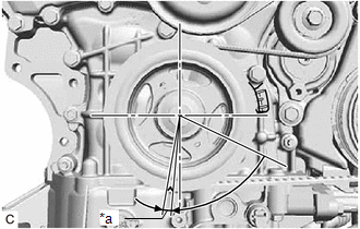
19. SET NO. 1 CYLINDER TO TDC (COMPRESSION)
|
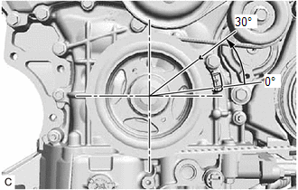
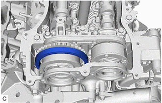
(a) Turn the crankshaft clockwise to align the timing mark (cutout) on the crankshaft pulley with the "0" timing mark on the timing chain cover assembly. |
|
|
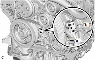
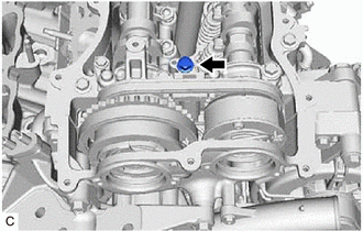
(b) Check that the timing marks of the camshaft timing gear assemblies are aligned with the timing marks of the camshaft bearing caps as shown in the illustration. HINT: If the marks are not aligned, turn the crankshaft again to align the marks. |
|
(c) Place paint marks on the timing marks and sprockets of each camshaft timing gear assembly and on the links of the chain sub-assembly.
HINT:
Be sure to place the paint marks on 2 links of the chain sub-assembly and on the sprockets of the camshaft timing gear assemblies at the locations of the timing marks of the camshaft timing gear assemblies.
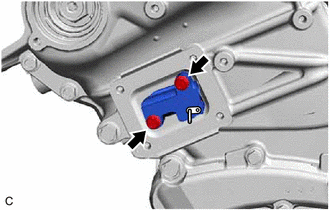
20. REMOVE NO. 1 CHAIN TENSIONER ASSEMBLY
|
(a) Turn the crankshaft approximately 30° counterclockwise so that there is some slack in the chain sub-assembly. HINT: This prevents the valves and pistons from interfering with each other. |
|
|
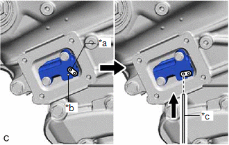
(b) Align the hole in the lever of the No. 1 chain tensioner assembly with the hole in the tensioner body as shown in the illustration, and then insert a pin with a diameter of 1.0 mm (0.0394 in.) into the hole. NOTICE: Check that the pin is locked. |
|
|
(c) Turn the crankshaft clockwise to align the timing mark (cutout) on the crankshaft pulley with the "0" timing mark on the timing chain cover assembly. |
|
|
(d) Remove the 2 bolts and No. 1 chain tensioner assembly from the cylinder head sub-assembly. NOTICE: Do not drop the No. 1 chain tensioner assembly or bolts into the timing chain cover assembly. |
|
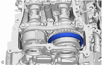
21. DISCONNECT CHAIN SUB-ASSEMBLY (for Bank 1)
|
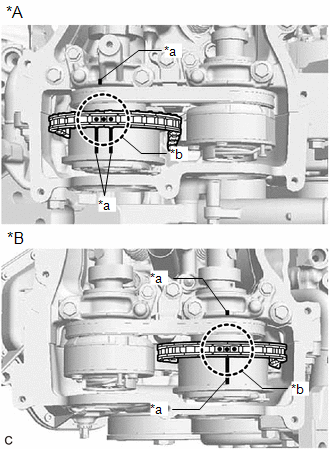
(a) Turn the crankshaft clockwise until it is in the position shown in the illustration so that there is some slack in the chain sub-assembly between the banks. CAUTION: As the camshafts turn suddenly, do not touch the camshafts or camshaft timing gears. HINT: When turning the crankshaft, engine oil may spray out of the oil holes. |
|

|
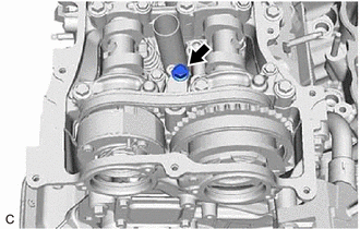
(b) Turn the crankshaft clockwise until it is in the position shown in the illustration so that the chain sub-assembly can be removed easily. HINT: When turning the crankshaft, engine oil may spray out of the oil holes. |
|
|
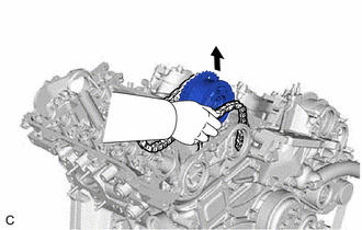
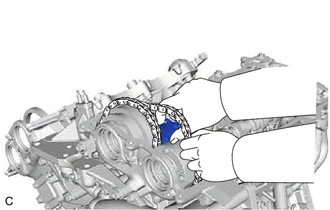
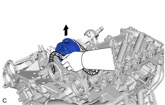
(c) Remove the chain sub-assembly from the sprocket of the camshaft timing gear assembly and set it on the camshaft timing gear assembly. CAUTION: As the camshaft may turn suddenly and pinch your fingers when the chain sub-assembly is removed, pinch the chain sub-assembly and lift it upward to remove it from the sprocket. |
|
22. SEPARATE NO. 2 CHAIN TENSIONER ASSEMBLY
|
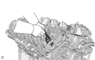
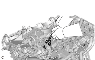
(a) Remove the bolt of the No. 2 chain tensioner assembly. |
|
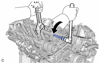
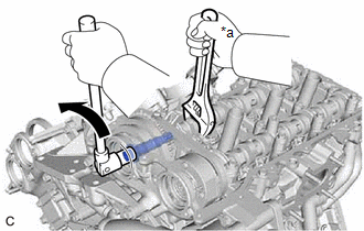
23. REMOVE CAMSHAFT TIMING GEAR BOLT (for Intake Side of Bank 1)
(a) Hold the hexagonal portion of the camshaft with a wrench and remove the camshaft timing gear bolt from the camshaft timing gear assembly.
|
*a |
Hold |

|
Turn |
NOTICE:
- Be careful not to damage the camshaft, camshaft housing sub-assembly or spark plug tube with the wrench.
- If the camshaft timing gear bolt has been struck or dropped, replace it.
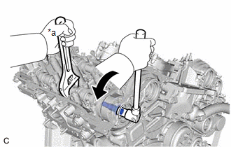
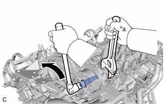
24. REMOVE CAMSHAFT TIMING GEAR BOLT (for Exhaust Side of Bank 1)
(a) Hold the hexagonal portion of the No. 2 camshaft with a wrench and remove the camshaft timing gear bolt from the camshaft timing exhaust gear assembly.
NOTICE:
- Be careful not to damage the camshaft, camshaft housing sub-assembly or spark plug tube with the wrench.
- If the camshaft timing gear bolt has been struck or dropped, replace it.
|
*a |
Hold |
|
|
Turn |
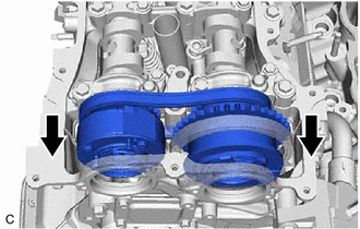
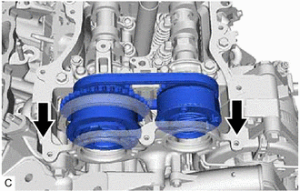
25. REMOVE CAMSHAFT BEARING CAP (for Bank 1)
|
(a) Slide the camshaft timing gear assembly and camshaft timing exhaust gear assembly as shown in the illustration. |
|
|
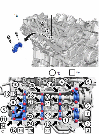
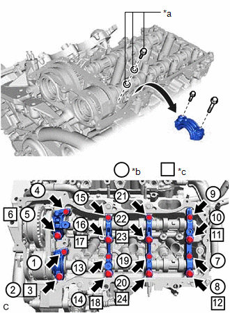
(b) Remove the bolts and camshaft bearing caps in the order shown in the illustration. Immediately after removing a camshaft bearing cap, install replacement bolts and washers in the order shown in the illustration. Torque: 10 N·m {102 kgf·cm, 7 ft·lbf} NOTICE:
HINT:
|
|
26. REMOVE NO. 2 CAMSHAFT
|
(a) While lifting up the camshaft timing exhaust gear assembly, remove the No. 2 chain tensioner assembly. |
|
(b) Lift up the rear of the No. 2 camshaft so that it is at an angle.
|
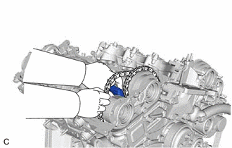
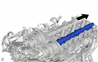
(c) Pull the No. 2 camshaft as shown in the illustration to remove it from the camshaft timing exhaust gear assembly. |
|
27. REMOVE CAMSHAFT
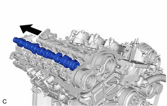
(a) Lift up the rear of the camshaft so that it is at an angle.
|
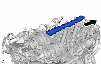
(b) Pull the camshaft as shown in the illustration to remove it from the camshaft timing gear assembly. |
|
28. REMOVE CAMSHAFT TIMING EXHAUST GEAR ASSEMBLY (for Bank 1)
|
(a) Remove the camshaft timing exhaust gear assembly. |
|
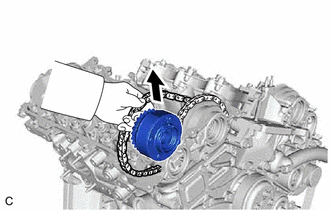
29. REMOVE CAMSHAFT TIMING GEAR ASSEMBLY (for Bank 1)
|
(a) Remove the camshaft timing gear assembly and No. 2 chain sub-assembly. NOTICE: Do not drop the chain sub-assembly into the gap between the engine and timing chain cover assembly. |
|
|
(b) Suspend the chain sub-assembly with a string or equivalent. |
|
30. DISCONNECT CHAIN SUB-ASSEMBLY (for Bank 2)
|
(a) Turn the crankshaft counterclockwise to align the timing mark (cutout) on the crankshaft pulley with the "0" timing mark on the timing chain cover assembly. |
|
|
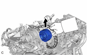
(b) Remove the chain sub-assembly from the sprocket of the camshaft timing gear assembly and set it on the camshaft timing gear assembly. CAUTION: As the camshaft may turn suddenly and pinch your fingers when the chain sub-assembly is removed, pinch the chain sub-assembly and lift it upward to remove it from the sprocket. |
|
31. SEPARATE NO. 3 CHAIN TENSIONER ASSEMBLY
|
(a) Remove the bolt of the No. 3 chain tensioner assembly. |
|
32. REMOVE CAMSHAFT TIMING GEAR BOLT (for Intake Side of Bank 2)
(a) Hold the hexagonal portion of the No. 3 camshaft sub-assembly with a wrench and remove the camshaft timing gear bolt from the camshaft timing gear assembly.
|
*a |
Hold |
|
|
Turn |
NOTICE:
- Be careful not to damage the No. 3 camshaft sub-assembly, camshaft housing sub-assembly LH or spark plug tube with the wrench.
- If the camshaft timing gear bolt has been struck or dropped, replace it.
33. REMOVE CAMSHAFT TIMING GEAR BOLT (for Exhaust Side of Bank 2)
(a) Hold the hexagonal portion of the No. 4 camshaft sub-assembly with a wrench and remove the camshaft timing gear bolt from the camshaft timing exhaust gear assembly.
|
*a |
Hold |
|
|
Turn |
NOTICE:
- Be careful not to damage the No. 4 camshaft sub-assembly, camshaft housing sub-assembly LH or spark plug tube with the wrench.
- If the camshaft timing gear bolt has been struck or dropped, replace it.
34. REMOVE CAMSHAFT BEARING CAP (for Bank 2)
|
(a) Slide the camshaft timing gear assembly and camshaft timing exhaust gear assembly as shown in the illustration. |
|
|
(b) Remove the bolts and camshaft bearing caps in the order shown in the illustration. Immediately after removing a camshaft bearing cap, install replacement bolts and washers in the order shown in the illustration. Torque: 10 N·m {102 kgf·cm, 7 ft·lbf} NOTICE:
HINT:
|
|
35. REMOVE NO. 4 CAMSHAFT SUB-ASSEMBLY
|
(a) While lifting up the camshaft timing exhaust gear assembly, remove the No. 3 chain tensioner assembly. |
|
(b) Lift up the rear of the No. 4 camshaft sub-assembly so that it is at an angle.
|
(c) Pull the No. 4 camshaft sub-assembly as shown in the illustration to remove it from the camshaft timing exhaust gear assembly. |
|
36. REMOVE NO. 3 CAMSHAFT SUB-ASSEMBLY
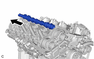
(a) Lift up the rear of the No. 3 camshaft sub-assembly so that it is at an angle.
|
(b) Pull the No. 3 camshaft sub-assembly as shown in the illustration to remove it from the camshaft timing gear assembly. |
|
37. REMOVE CAMSHAFT TIMING EXHAUST GEAR ASSEMBLY (for Bank 2)
|
(a) Remove the camshaft timing exhaust gear assembly. |
|
38. REMOVE CAMSHAFT TIMING GEAR ASSEMBLY (for Bank 2)
|
(a) Remove the camshaft timing gear assembly and No. 2 chain sub-assembly. NOTICE: Do not drop the chain sub-assembly into the gap between the engine and timing chain cover assembly. |
|
|
(b) Suspend the chain sub-assembly with a string or equivalent. |
|
|
|
|