| Last Modified: 08-28-2024 | 6.11:8.1.0 | Doc ID: RM100000000YSRD |
| Model Year Start: 2017 | Model: Sienna | Prod Date Range: [08/2016 - ] |
| Title: 2GR-FKS (ENGINE CONTROL): SFI SYSTEM: VC Output Circuit; 2017 - 2020 MY Sienna [08/2016 - ] | ||
|
VC Output Circuit |
DESCRIPTION
The ECM constantly uses 5 V from the battery voltages supplied to the +B (BATT) terminal to operate the microprocessor. The ECM also provides this power to the sensors through the VC output circuit.
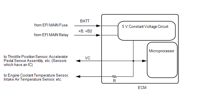
When the VC circuit is shorted, the microprocessor in the ECM and sensors that are supplied power through the VC circuit are inactivated because the power is not supplied from the VC circuit. Under this condition, the system does not start up and the MIL does not illuminate even if the system malfunctions.
HINT:
Under normal conditions, the MIL is illuminated for several seconds when the ignition switch is first turned ON. The MIL goes off when the engine is started.
WIRING DIAGRAM
CAUTION / NOTICE / HINT
NOTICE:
Check the fuses for circuits related to this system before performing the following inspection procedure.
PROCEDURE
|
1. |
CHECK MIL |
(a) Check that the Malfunction Indicator Lamp (MIL) illuminates when turning the ignition switch to ON.
Result |
Proceed to |
|---|---|
|
MIL does not light up |
A |
|
MIL lights up |
B |
| A |

|
PROCEED TO NEXT SUSPECTED AREA SHOWN IN PROBLEM SYMPTOMS TABLE
|
|

|
2. |
CHECK CONNECTION BETWEEN TECHSTREAM AND ECM |
(a) Connect the Techstream to the DLC3.
(b) Turn the ignition switch to ON.
(c) Turn the Techstream on.
(d) Check the communication between the Techstream and ECM.
HINT:
It can be checked using the "Engine" item of the Data List.
|
Result |
Proceed to |
|---|---|
|
Communication is not possible |
A |
|
Communication is possible |
B |
| B |
|
GO TO MIL CIRCUIT
|
|
|
3. |
CHECK MIL (THROTTLE POSITION SENSOR) |
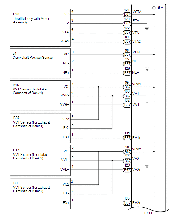
(a) Disconnect the B20 throttle body with motor assembly connector.
(b) Turn the ignition switch to ON.
(c) Check the MIL.
|
Result |
Proceed to |
|---|---|
|
MIL does not illuminate |
A |
|
MIL illuminates |
B |
HINT:
Perform "Inspection After Repair" after replacing the throttle body with motor assembly.
Click here
![2017 MY Sienna [08/2016 - 11/2017]; 2GR-FKS (ENGINE CONTROL): SFI SYSTEM: INITIALIZATION](/t3Portal/stylegraphics/info.gif)
| B |
|
|
|
4. |
CHECK MIL (ACCELERATOR PEDAL POSITION SENSOR) |
(a) Disconnect the A57 accelerator pedal sensor assembly connector.
(b) Turn the ignition switch to ON.
(c) Check the MIL.
|
Result |
Proceed to |
|---|---|
|
MIL does not illuminate |
A |
|
MIL illuminates |
B |
| B |
|
|
|
5. |
CHECK MIL (CRANKSHAFT POSITION SENSOR) |
(a) Disconnect the u1 crankshaft position sensor connector.
(b) Turn the ignition switch to ON.
(c) Check the MIL.
|
Result |
Proceed to |
|---|---|
|
MIL does not illuminate |
A |
|
MIL illuminates |
B |
| B |
|
|
|
6. |
CHECK MIL (VVT SENSOR (FOR INTAKE CAMSHAFT OF BANK 1)) |
(a) Disconnect the B16 VVT sensor (for intake camshaft of bank 1) connector.
(b) Turn the ignition switch to ON.
(c) Check the MIL.
|
Result |
Proceed to |
|---|---|
|
MIL does not illuminate |
A |
|
MIL illuminates |
B |
| B |
|
|
|
7. |
CHECK MIL (VVT SENSOR (FOR INTAKE CAMSHAFT OF BANK 2)) |
(a) Disconnect the B17 VVT sensor (for intake camshaft of bank 2) connector.
(b) Turn the ignition switch to ON.
(c) Check the MIL.
|
Result |
Proceed to |
|---|---|
|
MIL does not illuminate |
A |
|
MIL illuminates |
B |
| B |
|
|
|
8. |
CHECK MIL (VVT SENSOR (FOR EXHAUST CAMSHAFT OF BANK 1)) |
(a) Disconnect the BB37 VVT sensor (for exhaust camshaft of bank 1) connector.
(b) Turn the ignition switch to ON.
(c) Check the MIL.
|
Result |
Proceed to |
|---|---|
|
MIL does not illuminate |
A |
|
MIL illuminates |
B |
| B |
|
|
|
9. |
CHECK MIL (VVT SENSOR (FOR EXHAUST CAMSHAFT OF BANK 2)) |
(a) Disconnect the B36 VVT sensor (for exhaust camshaft of bank 2) connector.
(b) Turn the ignition switch to ON.
(c) Check the MIL.
|
Result |
Proceed to |
|---|---|
|
MIL does not illuminate |
A |
|
MIL illuminates |
B |
| B |
|
|
|
10. |
CHECK MIL (FUEL PRESSURE SENSOR (FOR HIGH PRESSURE SIDE)) |
(a) Disconnect the B64 fuel pressure sensor (for high pressure side) connector.
(b) Turn the ignition switch to ON.
(c) Check the MIL.
|
Result |
Proceed to |
|---|---|
|
MIL does not illuminate |
A |
|
MIL illuminates |
B |
HINT:
Perform "Inspection After Repair" after replacing the fuel pressure sensor (for high pressure side).
Click here
| B |
|
REPLACE FUEL DELIVERY PIPE WITH SENSOR ASSEMBLY LH (FUEL PRESSURE SENSOR (FOR HIGH PRESSURE SIDE)) |
|
|
11. |
CHECK MIL (FUEL PRESSURE SENSOR (FOR LOW PRESSURE SIDE)) |
(a) Disconnect the B59 fuel pressure sensor (for low pressure side) connector.
(b) Turn the ignition switch to ON.
(c) Check the MIL.
|
Result |
Proceed to |
|---|---|
|
MIL does not illuminate |
A |
|
MIL illuminates |
B |
HINT:
Perform "Inspection After Repair" after replacing the fuel pressure sensor (for low pressure side).
Click here
| B |
|
REPLACE FUEL DELIVERY PIPE SUB-ASSEMBLY (FUEL PRESSURE SENSOR (FOR LOW PRESSURE SIDE)) |
|
|
12. |
CHECK MIL (MASS AIR FLOW METER) |
(a) Disconnect the B56 mass air flow meter connector.
(b) Turn the ignition switch to ON.
(c) Check the MIL.
|
Result |
Proceed to |
|---|---|
|
MIL does not illuminate |
A |
|
MIL illuminates |
B |
| B |
|
|
|
13. |
CHECK MIL (CANISTER PUMP MODULE) |
(a) Disconnect the g1 canister pump module connector.
(b) Turn the ignition switch to ON.
(c) Check the MIL.
|
Result |
Proceed to |
|---|---|
|
MIL does not illuminate |
A |
|
MIL illuminates |
B |
| B |
|
|
|
14. |
CHECK HARNESS AND CONNECTOR |
(a) Disconnect the D20 throttle body with motor assembly connector.
(b) Disconnect the A57 accelerator pedal sensor assembly connector.
(c) Disconnect the u1 crankshaft position sensor connector.
(d) Disconnect the B16 VVT sensor (for intake camshaft of bank 1) connector.
(e) Disconnect the B17 VVT sensor (for intake camshaft of bank 2) connector.
(f) Disconnect the B37 VVT sensor (for exhaust camshaft of bank 1) connector.
(g) Disconnect the B36 VVT sensor (for exhaust camshaft of bank 2) connector.
(h) Disconnect the B64 fuel pressure sensor (for high pressure side) connector.
(i) Disconnect the B59 fuel pressure sensor (for low pressure side) connector.
(j) Disconnect the B56 mass air flow meter connector.
(k) Disconnect the A69 and B67 ECM connectors.
(l) Disconnect the g1 canister pump module connector.
(m) Measure the resistance according to the value(s) in the table below.
Standard Resistance:
|
Tester Connection |
Condition |
Specified Condition |
|---|---|---|
|
B67-121 (VCTA) - Body ground |
Always |
10 kΩ or higher |
|
A69-49 (VCPA) - Body ground |
Always |
10 kΩ or higher |
|
A69-52 (VCP2) - Body ground |
Always |
10 kΩ or higher |
|
B67-96 (VCNE) - Body ground |
Always |
10 kΩ or higher |
|
B67-99 (VCV1) - Body ground |
Always |
10 kΩ or higher |
|
B67-98 (VCV2) - Body ground |
Always |
10 kΩ or higher |
|
B67-90 (VC) - Body ground |
Always |
10 kΩ or higher |
|
A69-35 (VCPP) - Body ground |
Always |
10 kΩ or higher |
|
A69-2 (+B) - Body ground |
Always |
10 kΩ or higher |
|
A69-3 (+B2) - Body ground |
Always |
10 kΩ or higher |
| OK |
|
| NG |
|
REPAIR OR REPLACE HARNESS OR CONNECTOR |
|
|
|