| Last Modified: 08-28-2024 | 6.11:8.1.0 | Doc ID: RM100000000YS0T |
| Model Year Start: 2017 | Model: Sienna | Prod Date Range: [08/2016 - ] |
| Title: THEFT DETERRENT / KEYLESS ENTRY: THEFT DETERRENT SYSTEM: Ignition Switch Circuit; 2017 - 2020 MY Sienna [08/2016 - ] | ||
|
Ignition Switch Circuit |
DESCRIPTION
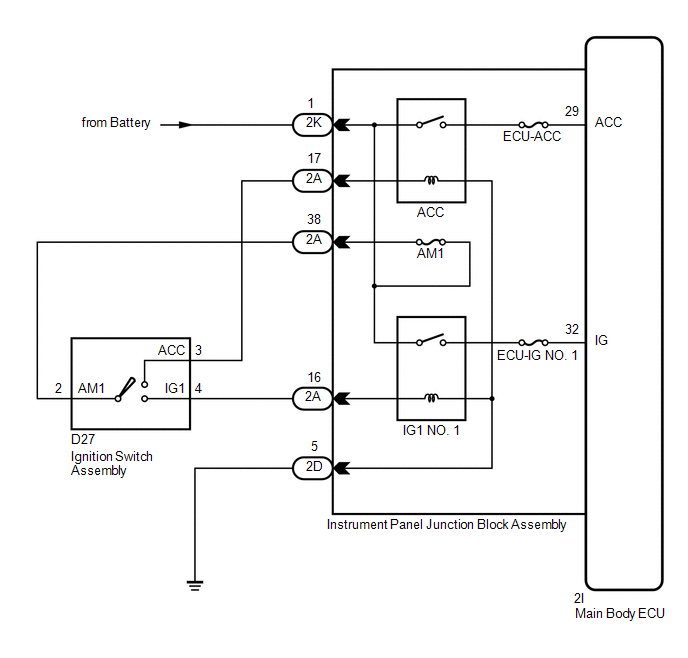
The main body ECU determines the ignition switch position (OFF, ACC, ON) based on signals from the IG or ACC circuit.
WIRING DIAGRAM
CAUTION / NOTICE / HINT
NOTICE:
Inspect the fuses for circuits related to this system before performing the following inspection procedure.
PROCEDURE
|
1. |
READ VALUE USING TECHSTREAM |
(a) Connect the Techstream to the DLC3.
(b) Turn the ignition switch to ON.
(c) Turn the Techstream on.
(d) Select the items below in the Data List and read the display on the Techstream.
Main Body
|
Tester Display |
Measurement Item/Range |
Normal Condition |
Diagnostic Note |
|---|---|---|---|
|
IG SW |
Ignition switch ON signal/ON or OFF |
ON: Ignition switch ON OFF: Ignition switch off |
- |
|
ACC SW |
Ignition switch ACC signal/ON or OFF |
ON: Ignition switch ACC OFF: Ignition switch off |
- |
OK:
When the ignition switch is operated, the display changes as shown in the table.
| OK |

|
PROCEED TO NEXT SUSPECTED AREA SHOWN IN PROBLEM SYMPTOMS TABLE |
|

|
2. |
CHECK HARNESS AND CONNECTOR (BATTERY - INSTRUMENT PANEL JUNCTION BLOCK) |
|
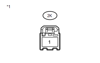
(a) Disconnect the 2K instrument panel junction block assembly connector. |
|
(b) Measure the voltage according to the value(s) in the table below.
Standard Voltage:
|
Tester Connection |
Condition |
Specified Condition |
|---|---|---|
|
2K-1 - Body ground |
Always |
11 to 14 V |
| NG |
|
REPAIR OR REPLACE HARNESS OR CONNECTOR |
|
|
3. |
INSPECT IGNITION SWITCH ASSEMBLY |
|
(a) Remove the ignition switch assembly (See page
|
|
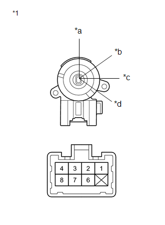
(b) Measure the resistance according to the value(s) in the table below.
Standard Resistance:
|
Tester Connection |
Switch Condition |
Specified Condition |
|---|---|---|
|
2 - 3 |
Ignition switch ON |
Below 1 Ω |
|
2 - 4 |
||
|
3 - 4 |
||
|
2 - 3 |
Ignition switch ACC |
Below 1 Ω |
| NG |
|
|
|
4. |
CHECK HARNESS AND CONNECTOR (IGNITION SWITCH - INSTRUMENT PANEL JUNCTION BLOCK) |
(a) Reinstall the ignition switch assembly (See page
![2017 - 2020 MY Sienna [08/2016 - ]; 2GR-FKS STARTING: IGNITION SWITCH: INSTALLATION](/t3Portal/stylegraphics/info.gif) ).
).
(b) Disconnect the 2A instrument panel junction block assembly connector.
(c) Measure the resistance according to the value(s) in the table below.
Standard Resistance:
|
Tester Connection |
Switch Condition |
Specified Condition |
|---|---|---|
|
2A-16 - 2A-38 |
Ignition switch ON |
Below 1 Ω |
|
2A-17 - 2A-38 |
Ignition switch ACC |
Below 1 Ω |
| NG |
|
REPAIR OR REPLACE HARNESS OR CONNECTOR |
|
|
5. |
CHECK HARNESS AND CONNECTOR (INSTRUMENT PANEL JUNCTION BLOCK ASSEMBLY - BODY GROUND) |
(a) Disconnect the 2D instrument panel junction block assembly connector.
(b) Measure the resistance according to the value(s) in the table below.
Standard Resistance:
|
Tester Connection |
Condition |
Specified Condition |
|---|---|---|
|
2D-5 - Body ground |
Always |
Below 1 Ω |
| NG |
|
REPAIR OR REPLACE HARNESS OR CONNECTOR |
|
|
6. |
REPLACE MULTIPLEX NETWORK BODY ECU |
(a) Temporarily replace the main body ECU with a new or normally functioning one (See page
).
|
|
7. |
READ VALUE USING TECHSTREAM |
(a) Connect the Techstream to the DLC3.
(b) Turn the ignition switch to ON.
(c) Turn the Techstream on.
(d) Select the items below in the Data List and read the display on the Techstream.
Main Body
|
Tester Display |
Measurement Item/Range |
Normal Condition |
Diagnostic Note |
|---|---|---|---|
|
IG SW |
Ignition switch ON signal/ON or OFF |
ON: Ignition switch ON OFF: Ignition switch off |
- |
|
ACC SW |
Ignition switch ACC signal/ON or OFF |
ON: Ignition switch ACC OFF: Ignition switch off |
- |
OK:
When the ignition switch is operated, the display changes as shown in the table.
| OK |
|
END (MAIN BODY ECU IS DEFECTIVE) |
| NG |
|
|
|
|