| Last Modified: 08-28-2024 | 6.11:8.1.0 | Doc ID: RM100000000YQW6 |
| Model Year Start: 2017 | Model: Sienna | Prod Date Range: [08/2016 - ] |
| Title: 2GR-FKS (INTAKE / EXHAUST): EXHAUST MANIFOLD: INSTALLATION; 2017 - 2020 MY Sienna [08/2016 - ] | ||
INSTALLATION
PROCEDURE
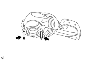
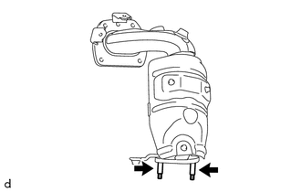
1. INSTALL STUD BOLT
HINT:
If a stud bolt is deformed or its threads are damaged, replace it.
|
(a) Using an E8 "TORX" socket wrench, install the 2 stud bolts to the exhaust manifold sub-assembly RH (TWC: front catalyst). Torque: 19.5 N·m {199 kgf·cm, 14 ft·lbf} |
|
|
(b) Using an E8 "TORX" socket wrench, install the 2 stud bolts to the exhaust manifold sub-assembly LH (TWC: front catalyst). Torque: 19.5 N·m {199 kgf·cm, 14 ft·lbf} |
|
2. INSTALL EXHAUST MANIFOLD TO HEAD GASKET (for Bank 2)
(a) Install a new exhaust manifold to head gasket to the cylinder head sub-assembly.
3. INSTALL EXHAUST MANIFOLD SUB-ASSEMBLY LH (TWC: Front Catalyst)
|
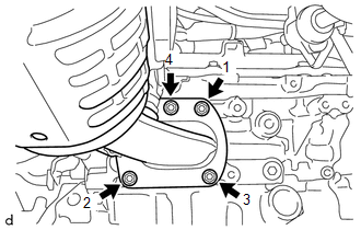
(a) Temporarily install the exhaust manifold sub-assembly LH with the 4 nuts. |
|
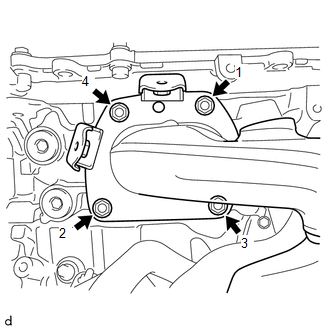
(b) Using a 12 mm deep socket wrench, tighten the 4 nuts in the order shown in the illustration.
Torque:
21 N·m {214 kgf·cm, 15 ft·lbf}
4. INSTALL AIR FUEL RATIO SENSOR (for Bank 2)
Click here
![2017 - 2020 MY Sienna [08/2016 - ]; 2GR-FKS (ENGINE CONTROL): AIR FUEL RATIO SENSOR: INSTALLATION+](/t3Portal/stylegraphics/info.gif)
5. INSTALL NO. 2 EXHAUST MANIFOLD HEAT INSULATOR
|
(a) Install the No. 2 exhaust manifold heat insulator, tightening the 3 bolts in the order shown in the illustration. Torque: 8.5 N·m {87 kgf·cm, 75 in·lbf} |
|
(b) Connect the air fuel ratio sensor (for bank 2) connector and engage the 2 harness clamps.
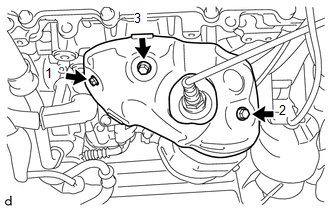
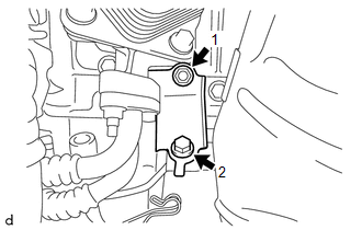
6. INSTALL NO. 2 MANIFOLD STAY
|
(a) Install the No. 2 manifold stay, tightening the bolt and nut in the order shown in the illustration. Torque: Bolt : 34 N·m {347 kgf·cm, 25 ft·lbf} Nut : 35 N·m {357 kgf·cm, 26 ft·lbf} |
|
7. INSTALL AIR FUEL RATIO SENSOR (for Bank 1)
Click here
8. INSTALL EXHAUST MANIFOLD TO HEAD GASKET (for Bank 1)
(a) Install a new exhaust manifold to head gasket.
9. INSTALL EXHAUST MANIFOLD SUB-ASSEMBLY RH (TWC: Front Catalyst)
|
(a) Temporarily install the exhaust manifold sub-assembly RH (TWC: front catalyst) with the 4 nuts. |
|
(b) Using a 12 mm deep socket wrench, tighten the 4 nuts in the order shown in the illustration.
Torque:
21 N·m {214 kgf·cm, 15 ft·lbf}
(c) Connect the air fuel ratio sensor (for bank 1) connector and engage the 3 harness clamps.
10. INSTALL MANIFOLD STAY
(a) Install the manifold stay with the bolt and nut.
Torque:
Bolt :
34 N·m {347 kgf·cm, 25 ft·lbf}
Nut :
35 N·m {357 kgf·cm, 26 ft·lbf}
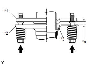
11. INSTALL FRONT EXHAUST PIPE ASSEMBLY (for 2WD)
(a) Inspect the free length.
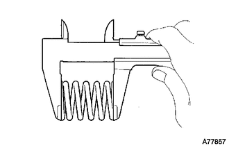
|
(1) Using a vernier caliper, measure the free length of the compression spring. Free Length of Compression Spring:
If the length is not as specified, replace the compression spring. |
|
|
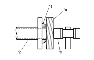
(b) Using a plastic hammer and a wooden block, tap in a new gasket until its surface is flush with the front exhaust pipe assembly. NOTICE:
|
|
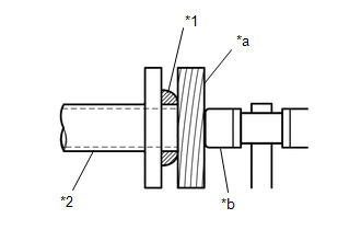
(c) Install 2 new gaskets to the front exhaust pipe assembly.
(d) Install the front exhaust pipe assembly to the exhaust manifold sub-assembly LH (TWC: front catalyst) and exhaust manifold sub-assembly RH (TWC: front catalyst) with 4 new nuts.
Torque:
43 N·m {438 kgf·cm, 32 ft·lbf}
|
(e) Connect the front exhaust pipe assembly to the center exhaust pipe sub-assembly (TWC: rear catalyst) with the 2 compression springs and 2 bolts. Torque: 43 N·m {438 kgf·cm, 32 ft·lbf} NOTICE: After the installation, check that the gaps between the flanges of the front exhaust pipe assembly and center exhaust pipe assembly are consistent front-to-rear and left-to-right. |
|
(f) Connect the exhaust pipe clamp to the No. 1 exhaust pipe support bracket and tighten the bolt.
Torque:
21 N·m {214 kgf·cm, 15 ft·lbf}
(g) Engage the 2 clamps to connect the heated oxygen sensor (for bank 2) wire to the wire harness clamp bracket.
(h) Connect the heated oxygen sensor (for bank 2) connector.
(i) Pass the connector through the hole to the inside of the vehicle and install the grommet of the heated oxygen sensor (for bank 1) wire.
(j) Connect the heated oxygen sensor (for bank 1) connector.
12. INSTALL FRONT EXHAUST PIPE ASSEMBLY (for AWD)
(a) Install a new gasket to the front exhaust pipe assembly.
(b) Install the front exhaust pipe assembly to the exhaust manifold sub-assembly LH (TWC: front catalyst) with 2 new nuts.
Torque:
43 N·m {438 kgf·cm, 32 ft·lbf}
(c) Inspect the free length.
|
(1) Using a vernier caliper, measure the free length of the compression spring. Free Length of Compression Spring:
If the length is not as specified, replace the compression spring. |
|
|
(d) Using a plastic hammer and a wooden block, tap in a new gasket until its surface is flush with the front No. 3 exhaust pipe sub-assembly. NOTICE:
|
|
(e) Install 2 new gaskets to the front No. 3 exhaust pipe sub-assembly.
(f) Install the front No. 3 exhaust pipe sub-assembly to the exhaust manifold sub-assembly RH (TWC: front catalyst) and front exhaust pipe assembly with 2 new nuts and 2 new bolts.
Torque:
43 N·m {438 kgf·cm, 32 ft·lbf}
|
(g) Connect the front No. 3 exhaust pipe sub-assembly to the center exhaust pipe sub-assembly LH (TWC: rear catalyst) with the 2 compression springs and 2 bolts. Torque: 43 N·m {438 kgf·cm, 32 ft·lbf} NOTICE: After the installation, check that the gaps between the flanges of the front No. 3 exhaust pipe sub-assembly and center exhaust pipe assembly are consistent front-to-rear and left-to-right. |
|

(h) Connect the exhaust pipe clamp to No. 1 exhaust pipe support bracket and tighten the bolt.
Torque:
21 N·m {214 kgf·cm, 15 ft·lbf}
(i) Engage the 2 clamps to connect the heated oxygen sensor (for bank 2) wire to the wire harness clamp bracket.
(j) Connect the heated oxygen sensor (for bank 2) connector.
(k) Pass the connector through the hole to the inside of the vehicle and install the grommet of the heated oxygen sensor (for bank 1) wire.
(l) Connect the heated oxygen sensor (for bank 1) connector.
13. INSTALL PROPELLER WITH CENTER BEARING SHAFT ASSEMBLY (for AWD)
Click here
14. INSTALL NO. 2 ENGINE UNDER COVER (for AWD)
(a) Install the No. 2 engine under cover with the 2 bolts, 2 screws and clip.
15. INSTALL NO. 1 ENGINE UNDER COVER
|
(a) Install the No. 1 engine under cover with the 2 bolts, 6 screws and 4 clips. |
|
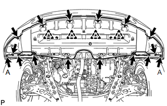
(b) Install the front wheel opening extension pad RH and front wheel opening extension pad LH with the 8 screws.
Torque:
Screw A :
7.0 N·m {71 kgf·cm, 62 in·lbf}
16. INSTALL INSTRUMENT PANEL FINISH PANEL END LH
-
for 2WD:
Click here
-
for AWD:
Click here
17. INSTALL RADIATOR ASSEMBLY
Click here
18. INSPECT FOR EXHAUST GAS LEAK
If gas is leaking, tighten the areas necessary to stop the leak. Replace damaged parts as necessary.
(a) Perform Inspection After Repair after repairing an exhaust gas leak.
Click here
19. INSTALL V-BANK COVER SUB-ASSEMBLY
Click here
|
|
|