| Last Modified: 08-28-2024 | 6.11:8.1.0 | Doc ID: RM100000000YQVX |
| Model Year Start: 2017 | Model: Sienna | Prod Date Range: [08/2016 - ] |
| Title: 2GR-FKS (INTAKE / EXHAUST): INTAKE MANIFOLD: INSTALLATION; 2017 - 2020 MY Sienna [08/2016 - ] | ||
INSTALLATION
PROCEDURE
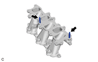
1. INSTALL STUD BOLT
HINT:
If a stud bolt is deformed or the threads are damaged, replace it.
|
(a) Using an E8 "TORX" socket wrench, install the 2 stud bolts to the intake manifold. Torque: 10 N·m {102 kgf·cm, 7 ft·lbf} |
|
2. INSTALL NO. 1 INTAKE MANIFOLD TO HEAD GASKET
(a) Install 2 new No. 1 intake manifold to head gaskets to each cylinder head sub-assembly.
NOTICE:
- Align the port holes of the No. 1 intake manifold to head gaskets and cylinder head sub-assembly.
- Make sure that the No. 1 intake manifold to head gaskets are installed in the correct direction.
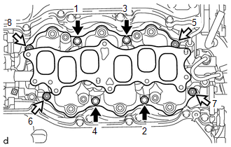
3. INSTALL INTAKE MANIFOLD
(a) Temporarily install the intake manifold to the cylinder head sub-assembly with the 4 bolts and 4 nuts.
(b) Tighten the 4 bolts and 4 nuts in the order shown in the illustration.

|
Bolt |

|
Nut |
Torque:
21 N·m {214 kgf·cm, 15 ft·lbf}
4. INSTALL INJECTOR VIBRATION INSULATOR
Click here
![2017 - 2020 MY Sienna [08/2016 - ]; 2GR-FKS (FUEL): FUEL INJECTOR(for Port Injection): INSTALLATION+](/t3Portal/stylegraphics/info.gif)
5. INSTALL NO. 1 DELIVERY PIPE SPACER
Click here
6. INSTALL FUEL DELIVERY PIPE WITH SENSOR ASSEMBLY
Click here
7. CONNECT FUEL TUBE SUB-ASSEMBLY
Click here
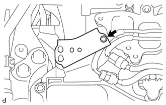
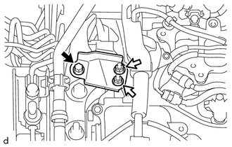
8. INSTALL NO. 2 ENGINE MOUNTING STAY RH
|
(a) Install the No. 2 engine mounting stay RH to the intake manifold with the bolt. Torque: 21 N·m {214 kgf·cm, 15 ft·lbf} |
|
|
(b) Install the wire harness clamp bracket to the No. 2 engine mounting stay RH with the bolt. Torque: 8.4 N·m {86 kgf·cm, 74 in·lbf} |
|
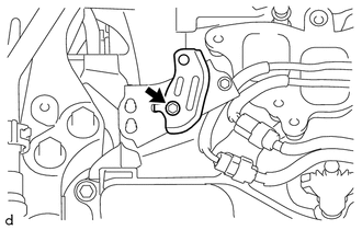
(c) Engage the wire harness clamp to the wire harness clamp bracket.
(d) Install the No. 2 engine mounting stay RH to the engine mounting insulator sub-assembly RH with the bolt and 2 nuts.
Torque:
Bolt :
38 N·m {387 kgf·cm, 28 ft·lbf}
Nut :
23 N·m {235 kgf·cm, 17 ft·lbf}
|
|
Bolt |
|
|
Nut |
9. INSTALL NO. 1 V-BANK COVER BRACKET
HINT:
Perform this procedure only when replacement of the No. 1 V-bank cover bracket is necessary.
(a) Install the 2 No. 1 V-bank cover brackets to the intake air surge tank assembly.
Torque:
9.0 N·m {92 kgf·cm, 80 in·lbf}
10. INSTALL AIR SURGE TANK TO INTAKE MANIFOLD GASKET
(a) Install a new air surge tank to intake manifold gasket to the intake air surge tank assembly.
11. INSTALL INTAKE AIR SURGE TANK ASSEMBLY
NOTICE:
Do not apply oil to the bolts and nuts as listed below:
|
Oil Application Prohibited Bolt and Nut |
|---|
|
Bolt and Nut for Intake Air Surge Tank Assembly and Intake Manifold |
|
Bolt for No. 2 Surge Tank Stay and Intake Air Surge Tank Assembly |
(a) Connect the vacuum hose sub-assembly to the intake air surge tank assembly.
(b) Temporarily install the intake air surge tank assembly to the intake manifold with the 5 bolts and 2 nuts.
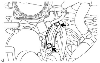
(c) Temporarily install the No. 2 surge tank stay to the intake manifold and camshaft housing RH with the 2 bolts.
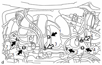
(d) Tighten the 5 bolts and 2 nuts in the order shown in the illustration.
Torque:
21 N·m {214 kgf·cm, 15 ft·lbf}
|
|
Bolt |
|
|
Nut |
|
(e) Tighten the 2 bolts in the order shown in the illustration. Torque: 21 N·m {214 kgf·cm, 15 ft·lbf} |
|
|
(f) Engage the clamp to connect the No. 2 air tube to the intake air surge tank assembly. |
|
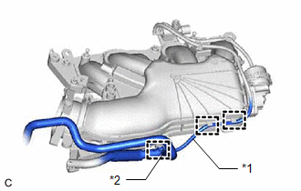
(g) Engage the 2 clamps to connect the vacuum hose sub-assembly to the intake air surge tank assembly.
|
(h) Engage the 5 clamps to connect the vacuum hose sub-assembly to the intake air surge tank assembly. |
|
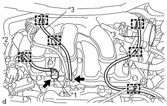
(i) Engage the wire harness clamp to the intake air surge tank assembly.
(j) Connect the No. 1 vacuum switching valve assembly (for ACIS) connector.
12. CONNECT PURGE VALVE (PURGE VSV)
(a) Connect the purge valve (purge VSV) to the intake air surge tank assembly with the bolt.
Torque:
21 N·m {214 kgf·cm, 15 ft·lbf}
(b) Connect the No. 1 fuel vapor feed hose to the intake air surge tank assembly.
(c) Connect the purge valve (purge VSV) connector.
13. CONNECT VENTILATION HOSE
(a) Connect the ventilation hose to the intake air surge tank assembly and slide the clip to secure it.
14. INSTALL THROTTLE BODY WITH MOTOR ASSEMBLY
Click here
15. INSTALL COWL PANEL SUB-ASSEMBLY
Click here
16. INSTALL WINDSHIELD WIPER MOTOR AND LINK
Click here
17. CONNECT CABLE TO NEGATIVE BATTERY TERMINAL
NOTICE:
When disconnecting the cable, some systems need to be initialized after the cable is reconnected.
Click here
18. INSPECT FOR FUEL LEAK
Click here
19. INSTALL V-BANK COVER SUB-ASSEMBLY
Click here
|
|
|