- ON: Shift lever in S, "+" or "-"
- OFF: Shift lever not in S, "+" or "-"
| Last Modified: 08-28-2024 | 6.11:8.1.0 | Doc ID: RM100000000YIZL |
| Model Year Start: 2017 | Model: Sienna | Prod Date Range: [08/2016 - ] |
| Title: UA80E (AUTOMATIC TRANSMISSION / TRANSAXLE): AUTOMATIC TRANSAXLE SYSTEM: Transmission Control Switch Circuit; 2017 - 2020 MY Sienna [08/2016 - ] | ||
|
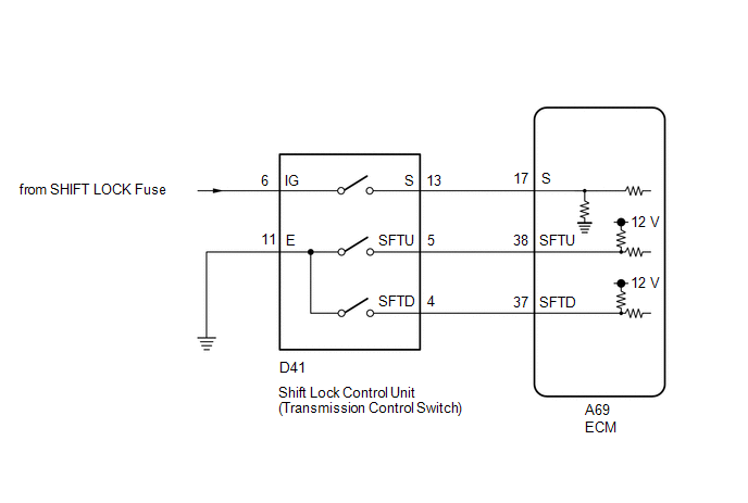
Transmission Control Switch Circuit |
DESCRIPTION
When the shift lever is in S and moved toward "-" or "+", it is possible to select different shift ranges (S1 to S8).
Moving the shift lever toward "+" increases the shift range by one, and moving the shift lever toward "-" decreases the shift range by one.
WIRING DIAGRAM
CAUTION / NOTICE / HINT
NOTICE:
Inspect the fuses for circuits related to this system before performing the following procedure.
PROCEDURE
|
1. |
READ VALUE USING TECHSTREAM (SHIFT SW STATUS (S RANGE)) |
(a) Connect the Techstream to the DLC3.
(b) Turn the ignition switch to ON.
(c) Turn the Techstream on.
(d) Enter the following menus: Powertrain / Transmission / Data List
(e) Read the Data List according to the display on the Techstream.
Transmission
|
Tester Display |
Measurement Item |
Range |
Normal Condition |
Diagnostic Note |
|---|---|---|---|---|
|
Shift SW Status (S Range) |
Sport (S) mode select switch status |
ON or OFF |
|
- |
|
Result |
Proceed to |
|---|---|
|
Data List values are normal |
A |
|
Data List values are not normal |
B |
| B |

|
|

|
2. |
READ VALUE USING TECHSTREAM (SPORT SHIFT UP SW AND SPORT SHIFT DOWN SW) |
(a) Connect the Techstream to the DLC3.
(b) Turn the ignition switch to ON.
(c) Turn the Techstream on.
(d) Enter the following menus: Powertrain / Engine / Data List
(e) Read the Data List according to the display on the Techstream.
Engine
|
Tester Display |
Measurement Item |
Range |
Normal Condition |
Diagnostic Note |
|---|---|---|---|---|
|
Sport Shift Up SW |
Sport shift up switch status |
ON or OFF |
|
- |
|
Sport Shift Down SW |
Sport shift down switch status |
ON or OFF |
|
- |
|
Result |
Proceed to |
|---|---|
|
Data List values are normal |
A |
|
Data List values are not normal |
B |
| A |
|
PROCEED TO NEXT SUSPECTED AREA SHOWN IN PROBLEM SYMPTOMS TABLE |
|
|
3. |
INSPECT SHIFT LOCK CONTROL UNIT ASSEMBLY (TRANSMISSION CONTROL SWITCH) |
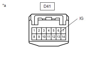
(a) Disconnect the D41 transmission control switch connector.
|
(b) Measure the resistance according to the value(s) in the table below. Standard Resistance:
|
|
| NG |
|
REPLACE SHIFT LOCK CONTROL UNIT ASSEMBLY (TRANSMISSION CONTROL SWITCH) |
|
|
4. |
CHECK HARNESS AND CONNECTOR (TRANSMISSION CONTROL SWITCH - BODY GROUND) |
|
(a) Disconnect the transmission control switch connector. |
|
(b) Measure the resistance according to the value(s) in the table below.
Standard Resistance:
|
Tester Connection |
Condition |
Specified Condition |
|---|---|---|
|
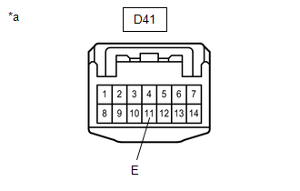
D41-11 (E) - Body ground |
Always |
Below 1 Ω |
| NG |
|
REPAIR OR REPLACE HARNESS OR CONNECTOR |
|
|
5. |
CHECK HARNESS AND CONNECTOR (TRANSMISSION CONTROL SWITCH - ECM) |
(a) Connect the D41 transmission control switch connector.
(b) Disconnect the A69 ECM connector.
(c) Measure the resistance according to the value(s) in the table below.
Standard Resistance:
|
Tester Connection |
Condition |
Specified Condition |
|---|---|---|
|
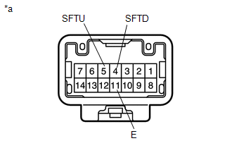
A69-38 (SFTU) - Body ground |
Shift lever held in "+" (Up shift) |
Below 1 Ω |
|
Shift lever not held in "+" (Up shift) |
10 kΩ or higher |
|
|
A69-37 (SFTD) - Body ground |
Shift lever held in "-" (Down shift) |
Below 1 Ω |
|
Shift lever not held in "-" (Down shift) |
10 kΩ or higher |
| OK |
|
PROCEED TO NEXT SUSPECTED AREA SHOWN IN PROBLEM SYMPTOMS TABLE |
| NG |
|
REPAIR OR REPLACE HARNESS OR CONNECTOR (TRANSMISSION CONTROL SWITCH - ECM) |
|
6. |
INSPECT SHIFT LOCK CONTROL UNIT ASSEMBLY (TRANSMISSION CONTROL SWITCH) |
|
(a) Disconnect the D41 transmission control switch connector. |
|
(b) Measure the resistance according to the value(s) in the table below.
Standard Resistance:
|
Tester Connection |
Condition |
Specified Condition |
|---|---|---|
|
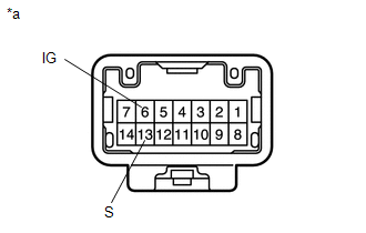
6 (IG) - 13 (S) |
Shift lever in S, "+" or "-" |
Below 1 Ω |
|
Shift lever not in S, "+" or "-" |
10 kΩ or higher |
| NG |
|
REPLACE SHIFT LOCK CONTROL UNIT ASSEMBLY (TRANSMISSION CONTROL SWITCH) |
|
|
7. |
CHECK HARNESS AND CONNECTOR (TRANSMISSION CONTROL SWITCH (POWER SOURCE)) |
|
(a) Disconnect the transmission control switch connector. |
|
(b) Turn the ignition switch to ON.
(c) Measure the voltage according to the value(s) in the table below.
Standard Voltage:
|
Tester Connection |
Switch Condition |
Specified Condition |
|---|---|---|
|
D41-6 (IG) - Body ground |
Ignition switch ON |
11 to 14 V |
| NG |
|
REPAIR OR REPLACE HARNESS OR CONNECTOR |
|
|
8. |
CHECK HARNESS AND CONNECTOR (TRANSMISSION CONTROL SWITCH - ECM) |
(a) Disconnect the D41 transmission control switch connector.
(b) Disconnect the A69 ECM connector.
(c) Measure the resistance according to the value(s) in the table below.
Standard Resistance:
|
Tester Connection |
Condition |
Specified Condition |
|---|---|---|
|
D41-13 (S) - A69-17 (S) |
Always |
Below 1 Ω |
|
D41-13 (S) or A69-17 (S) - Body ground and other terminals |
Always |
10 kΩ or higher |
| OK |
|
PROCEED TO NEXT SUSPECTED AREA SHOWN IN PROBLEM SYMPTOMS TABLE |
| NG |
|
REPAIR OR REPLACE HARNESS OR CONNECTOR |
|
|
|