- DTC judgment completed
- System normal
| Last Modified: 08-28-2024 | 6.11:8.1.0 | Doc ID: RM100000000YIZB |
| Model Year Start: 2017 | Model: Sienna | Prod Date Range: [08/2016 - 11/2017] |
| Title: UA80E (AUTOMATIC TRANSMISSION / TRANSAXLE): AUTOMATIC TRANSAXLE SYSTEM: P271312,P271314; Pressure Control Solenoid "D" Circuit Short to Battery; 2017 MY Sienna [08/2016 - 11/2017] | ||
|
DTC |
P271312 |
Pressure Control Solenoid "D" Circuit Short to Battery |
|
DTC |
P271314 |
Pressure Control Solenoid "D" Circuit Short to Ground or Open |
DESCRIPTION
Refer to DTC P27137F.
Click here
![2017 MY Sienna [08/2016 - 11/2017]; UA80E (AUTOMATIC TRANSMISSION / TRANSAXLE): AUTOMATIC TRANSAXLE SYSTEM: P27137F; Pressure Control Solenoid "D" Actuator Stuck Off+](/t3Portal/stylegraphics/info.gif)
|
DTC No. |
Detection Item |
DTC Detection Condition |
Trouble Area |
MIL |
Memory |
Note |
|---|---|---|---|---|---|---|
|
P271312 |
Pressure Control Solenoid "D" Circuit Short to Battery |
1. Diagnosis Condition 2.Malfunction Status 3. Malfunction Time 4. Other
|
|
Comes on |
DTC stored |
SAE Code: P2721 |
|
P271314 |
Pressure Control Solenoid "D" Circuit Short to Ground or Open |
1. Diagnosis Condition 2.Malfunction Status 3. Malfunction Time 4. Other
|
|
Comes on |
DTC stored |
SAE Code: P2720 |
MONITOR DESCRIPTION
When an open or short to +B and ground in the shift solenoid valve SLT circuit is detected, the ECM will determine that there is a malfunction, illuminate the MIL and store this DTC.
MONITOR STRATEGY
|
Related DTC |
P2720: Shift solenoid valve SLT/Range check (Low current) P2721: Shift solenoid valve SLT/Range check (High current) P2721: Shift solenoid valve SLT/Range check (High voltage) |
|
Required sensors/Components |
Shift solenoid valve SLT |
|
Frequency of operation |
Continuous |
|
Duration |
P2720: 1 sec. P2721: 1 sec. (High current), 1.3 sec. (High voltage) |
|
MIL operation |
Immediate |
|
Sequence of operation |
None |
TYPICAL ENABLING CONDITIONS
All
|
Solenoid current cut status |
Not cut |
|
Battery voltage |
8 V or more |
|
Ignition Switch |
ON |
|
Starter |
OFF |
P2720
|
The monitor will run whenever the following DTCs are not present |
None |
|
Battery voltage |
10.5 V or more |
|
Target current |
0.2 A or more |
P2721
|
The monitor will run whenever the following DTCs are not present |
None |
|
Battery voltage |
10.5 V or more |
High current Condition
|
Following condition is met |
Condition a. or b. |
|
a. Battery voltage |
8 V or more and less than 12.499 V |
|
Target current |
0.8 A or less |
|
b. Battery voltage |
12.5 V or more and less than 16 V |
|
Target current |
1 A or less |
High voltage Condition
|
Battery voltage |
10.5 V or more |
|
Target current |
0.2 A or more |
|
Output duty cycle |
10% or more and 90% or less |
TYPICAL MALFUNCTION THRESHOLDS
P2720
-
Solenoid current
Less than 0.075 A
Solenoid high current cutout by solenoid driver IC
ON
P2721
-
High current
Solenoid current
a. or b.
a. Battery voltage
8 V or more and less than 12.499 V
Target current
More than 0.92 A
b. Battery voltage
12.5 V or more and less than 16 V
Target current
More than 1.1 A
High voltage
Solenoid voltage monitor
No signal
COMPONENT OPERATING RANGE
P2720
-
Solenoid current
0.075 A or more
Solenoid high current cutout by solenoid driver IC
OFF
P2721
-
High current
Solenoid current
a. or b.
a. Battery voltage
8 V or more and less than 12.499 V
Target current
0.92 A or less
b. Battery voltage
12.5 V or more and less than 16 V
Target current
1.1 A or less
High voltage
Solenoid voltage monitor
Signal input
CONFIRMATION DRIVING PATTERN
HINT:
- After repairs have been completed, clear the DTCs and then check that the vehicle has returned to normal by performing the following All Readiness check procedure.
-
When clearing the permanent DTCs, refer to the Clear Permanent DTC procedure.
Click here
- Connect the Techstream to the DLC3.
- Turn the ignition switch to ON and turn the Techstream on.
- Clear the DTCs (even if no DTCs are stored, perform the clear DTC procedure).
- Turn the ignition switch off and wait for 2 minutes or more.
- Turn the ignition switch to ON and turn the Techstream on.
- Start the engine.
-
Wait for 2 seconds or more with the engine running. [*1]
HINT:
[*1] : Normal judgment procedure.
The normal judgment procedure is used to complete DTC judgment and also used when clearing permanent DTCs.
- Enter the following menus: Powertrain / Transmission / Utility / All Readiness.
- Input the DTC: P271312 or P271314.
-
Check the DTC judgment result.
Techstream Display
Description
NORMAL
ABNORMAL
- DTC judgment completed
- System abnormal
INCOMPLETE
- DTC judgment not completed
- Perform driving pattern after confirming DTC enabling conditions
N/A
- Unable to perform DTC judgment
- Number of DTCs which do not fulfill DTC preconditions has reached ECU memory limit
HINT:
- If the judgment result shows NORMAL, the system is normal.
- If the judgment result shows ABNORMAL, the system has a malfunction.
- If the judgment result shows INCOMPLETE or N/A, perform the normal judgment procedure again.
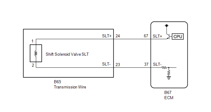
WIRING DIAGRAM
CAUTION / NOTICE / HINT
NOTICE:
-
Perform the universal trip to clear permanent DTCs.
Click here
-
Perform registration and/or initialization when parts related to the automatic transaxle are replaced.
Click here
PROCEDURE
|
1. |
CHECK HARNESS AND CONNECTOR (TRANSMISSION WIRE (SHIFT SOLENOID VALVE SLT) - ECM) |
(a) Disconnect the B67 ECM connector.
(b) Measure the resistance according to the value(s) in the table below.
Standard Resistance:
|
Tester Connection |
Condition |
Specified Condition |
|---|---|---|
|
B67-67 (SLT+) - B67-37 (SLT-) |
20°C (68°F) |
5.0 to 5.6 Ω |
|
B67-67 (SLT+) or B67-37 (SLT-) - Body ground and other terminals |
Always |
10 kΩ or higher |
| NG |

|
|

|
2. |
REPLACE ECM |
(a) Replace the ECM.
Click here
| NEXT |
|
|
3. |
CHECK HARNESS AND CONNECTOR (TRANSMISSION WIRE - ECM) |
(a) Disconnect the B65 transmission wire connector.
(b) Disconnect the B67 ECM connector.
(c) Measure the resistance according to the value(s) in the table below.
Standard Resistance:
|
Tester Connection |
Condition |
Specified Condition |
|---|---|---|
|
B65-24 (SLT+) - B67-67 (SLT+) |
Always |
Below 1 Ω |
|
B65-23 (SLT-) - B67-37 (SLT-) |
Always |
Below 1 Ω |
|
B65-24 (SLT+) or B67-67 (SLT+) - Body ground and other terminals |
Always |
10 kΩ or higher |
|
B65-23 (SLT-) or B67-37 (SLT-) - Body ground and other terminals |
Always |
10 kΩ or higher |
| NG |
|
REPAIR OR REPLACE HARNESS OR CONNECTOR (TRANSMISSION WIRE - ECM) |
|
|
4. |
INSPECT SHIFT SOLENOID VALVE SLT |
|
(a) Remove the shift solenoid valve SLT. Click here
|
|
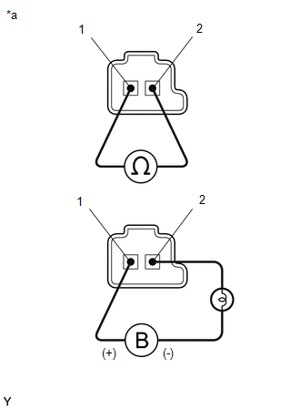
(b) Measure the resistance according to the value(s) in the table below.
Standard Resistance:
|
Tester Connection |
Condition |
Specified Condition |
|---|---|---|
|
Shift solenoid valve SLT connector terminal 1 - terminal 2 |
20°C (68°F) |
5.0 to 5.6 Ω |
(c) Connect a positive (+) lead from the battery to terminal 1 and a negative (-) lead with a 21 W bulb to terminal 2 of the solenoid valve connector. Check that the valve moves and makes an operating sound.
OK:
Valve moves and makes an operating sound.
| OK |
|
| NG |
|
|
|
|