| Last Modified: 08-28-2024 | 6.11:8.1.0 | Doc ID: RM100000000VKHY |
| Model Year Start: 2016 | Model: Sienna | Prod Date Range: [12/2015 - ] |
| Title: LIGHTING (EXT): LIGHTING SYSTEM: Headlight (HI-BEAM) Circuit; 2016 - 2020 MY Sienna [12/2015 - ] | ||
|
Headlight (HI-BEAM) Circuit |
DESCRIPTION
The main body ECU controls the high beam headlights.
WIRING DIAGRAM
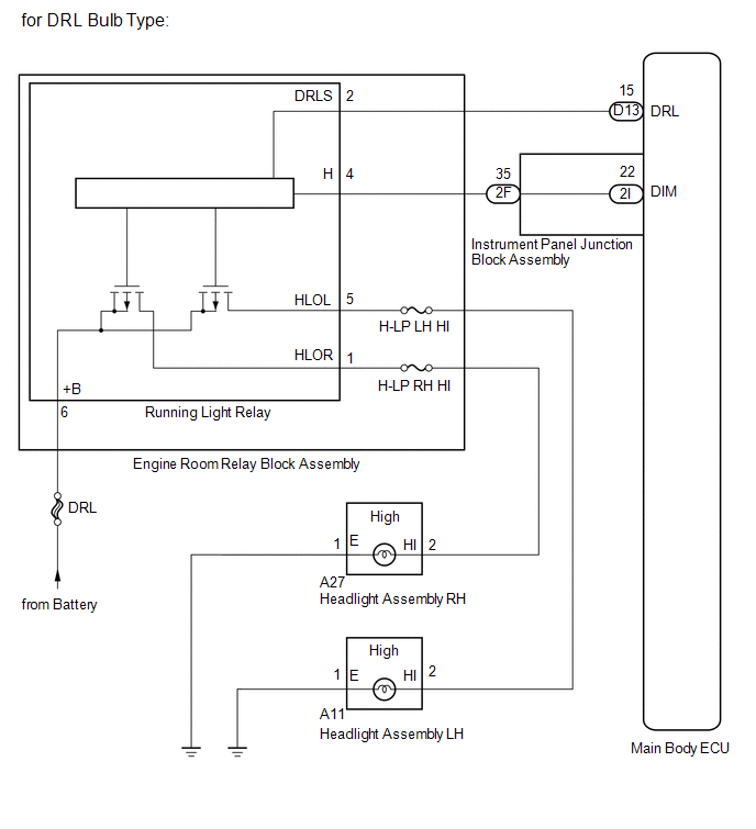
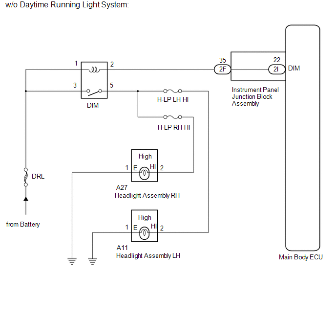
CAUTION / NOTICE / HINT
NOTICE:
Inspect the fuses for circuits related to this system before performing the following inspection procedure.
PROCEDURE
|
1. |
CHECK HEADLIGHT |
(a) Check the operation of low beam headlights.
OK:
Low beam headlights operate normally.
| NG |

|
GO TO PROBLEM SYMPTOMS TABLE (See page
|
![2016 MY Sienna [12/2015 - 08/2016]; LIGHTING (EXT): LIGHTING SYSTEM: PROBLEM SYMPTOMS TABLE](/t3Portal/stylegraphics/info.gif)
|

|
2. |
PERFORM ACTIVE TEST USING TECHSTREAM (HEAD LIGHT HI) |
(a) Connect the Techstream to the DLC3.
(b) Turn the ignition switch to ON.
(c) Turn the Techstream on.
(d) Enter the following menus: Body Electrical / Main Body / Active Test.
(e) Check that the relay operates.
Main Body
|
Tester Display |
Test Part |
Control Range |
Diagnostic Note |
|---|---|---|---|
|
Head Light HI |
High beam headlight relay |
ON/OFF |
- |
OK:
Relay operates. (High beam headlights illuminate.)
Result
|
Result |
Proceed to |
|---|---|
|
OK |
A |
|
NG (w/ Daytime running light system) |
B |
|
NG (w/o Daytime running light system) |
C |
| A |
|
| C |
|
|
|
3. |
INSPECT RUNNING LIGHT RELAY |
(a) Remove the running light relay from the engine room relay block assembly.
|
(b) Connect the positive (+) lead from the battery to terminal 6 (+B). |
|
(c) Connect the negative (-) lead from the battery to terminal 4 (H).
(d) Measure the voltage according to the value(s) in the table below.
Standard Voltage:
|
Tester Connection |
Condition |
Specified Condition |
|---|---|---|
|
1 (HLOR) - Body ground |
Battery voltage not applied |
Below 1 V |
|
5 (HLOL) - Body ground |
Below 1 V |
|
|
1 (HLOR) - Body ground |
Battery voltage applied to terminal 6 (+B) and 4 (H) |
11 to 14 V |
|
5 (HLOL) - Body ground |
11 to 14 V |
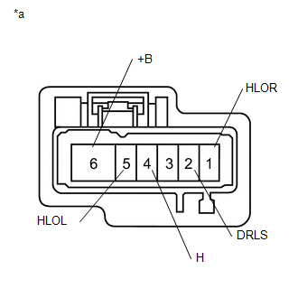
Text in Illustration
|
*a |
Component without harness connected (Running Light Relay) |
| NG |
|
|
|
4. |
CHECK HARNESS AND CONNECTOR (RUNNING LIGHT RELAY - INSTRUMENT PANEL JUNCTION BLOCK) |
(a) Remove the running light relay from the engine room relay block assembly.
(b) Disconnect the 2F instrument panel junction block assembly connector.
(c) Measure the resistance according to the value(s) in the table below.
Standard Resistance:
|
Tester Connection |
Condition |
Specified Condition |
|---|---|---|
|
4 (H) - 2F-35 |
Always |
Below 1 Ω |
|
4 (H) or 2F-35 - Body ground |
Always |
10 kΩ or higher |
| NG |
|
REPAIR OR REPLACE HARNESS OR CONNECTOR |
|
|
5. |
INSPECT INSTRUMENT PANEL JUNCTION BLOCK ASSEMBLY |
|
(a) Remove the instrument panel junction block assembly. |
|
(b) Measure the resistance according to the value(s) in the table below.
Standard Resistance:
|
Tester Connection |
Condition |
Specified Condition |
|---|---|---|
|
2F-35 - 2I-22 (DIM) |
Always |
Below 1 Ω |
|
2F-35 or 2I-22 (DIM) - Body ground |
Always |
10 kΩ or higher |
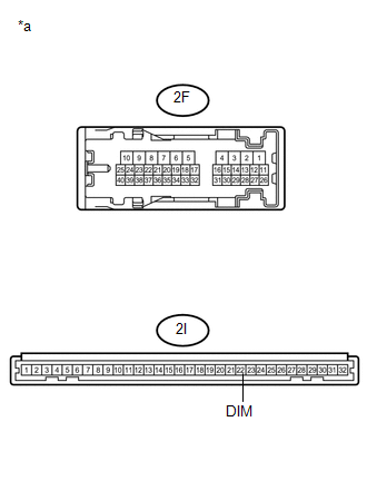
Text in Illustration
|
*a |
Component without harness connected (Instrument Panel Junction Block Assembly) |
| OK |
|
| NG |
|
REPLACE INSTRUMENT PANEL JUNCTION BLOCK ASSEMBLY |
|
6. |
INSPECT HEADLIGHT DIMMER RELAY |
|
(a) Remove the DIM (headlight dimmer) relay from the engine room relay block assembly. |
|
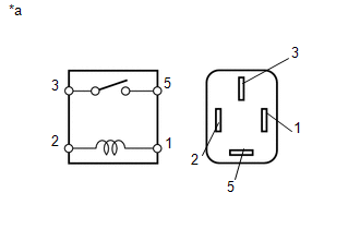
(b) Measure the resistance according to the value(s) in the table below.
Standard Resistance:
|
Tester Connection |
Condition |
Specified Condition |
|---|---|---|
|
3 - 5 |
Battery voltage not applied |
10 kΩ or higher |
|
Battery voltage applied between terminals 1 and 2 |
Below 1 Ω |
Text in Illustration
|
*a |
Component without harness connected (Headlight Dimmer Relay) |
| NG |
|
REPLACE HEADLIGHT DIMMER RELAY |
|
|
7. |
CHECK HARNESS AND CONNECTOR (HEADLIGHT DIMMER RELAY - INSTRUMENT PANEL JUNCTION BLOCK) |
(a) Remove the headlight dimmer relay from the engine room relay block assembly.
(b) Disconnect the 2F instrument panel junction block assembly connector.
(c) Measure the resistance according to the value(s) in the table below.
Standard Resistance:
|
Tester Connection |
Condition |
Specified Condition |
|---|---|---|
|
2 - 2F-35 |
Always |
Below 1 Ω |
|
2 or 2F-35 - Body ground |
Always |
10 kΩ or higher |
| NG |
|
REPAIR OR REPLACE HARNESS OR CONNECTOR |
|
|
8. |
INSPECT INSTRUMENT PANEL JUNCTION BLOCK ASSEMBLY |
|
(a) Remove the instrument panel junction block assembly. |
|
(b) Measure the resistance according to the value(s) in the table below.
Standard Resistance:
|
Tester Connection |
Condition |
Specified Condition |
|---|---|---|
|
2F-35 - 2I-22 (DIM) |
Always |
Below 1 Ω |
|
2F-35 or 2I-22 (DIM) - Body ground |
Always |
10 kΩ or higher |
Text in Illustration
|
*a |
Component without harness connected (Instrument Panel Junction Block Assembly) |
| OK |
|
| NG |
|
REPLACE INSTRUMENT PANEL JUNCTION BLOCK ASSEMBLY |
|
|
|