| Last Modified: 08-28-2024 | 6.11:8.1.0 | Doc ID: RM100000000VKHN |
| Model Year Start: 2016 | Model: Sienna | Prod Date Range: [12/2015 - ] |
| Title: LIGHTING (EXT): LIGHTING SYSTEM: Parking Brake Switch Circuit; 2016 - 2020 MY Sienna [12/2015 - ] | ||
|
Parking Brake Switch Circuit |
DESCRIPTION
The main body ECU detects the condition of the parking brake switch.
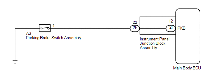
WIRING DIAGRAM
PROCEDURE
|
1. |
READ VALUE USING TECHSTREAM (PARKING BRAKE SW) |
(a) Connect the Techstream to the DLC3.
(b) Turn the ignition switch to ON.
(c) Turn the Techstream on.
(d) Enter the following menus: Body Electrical / Main Body / Data List.
(e) Read the display on the Techstream.
Main Body
|
Tester Display |
Measurement Item/Range |
Normal Condition |
Diagnostic Note |
|---|---|---|---|
|
Parking Brake SW |
Parking brake SW signal/ON or OFF |
ON: Parking brake switch on OFF: Parking brake switch off |
- |
OK:
Normal conditions listed above are displayed.
| OK |

|
PROCEED TO NEXT SUSPECTED AREA SHOWN IN PROBLEM SYMPTOMS TABLE (See page
|
![2016 MY Sienna [12/2015 - 08/2016]; LIGHTING (EXT): LIGHTING SYSTEM: PROBLEM SYMPTOMS TABLE](/t3Portal/stylegraphics/info.gif)
|

|
2. |
INSPECT PARKING BRAKE SWITCH ASSEMBLY |
|
(a) Remove the parking brake switch assembly (See page
|
|
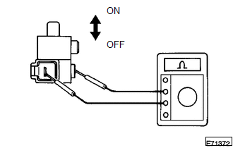
(b) Measure the resistance according to the value(s) in the table below.
Standard Resistance:
|
Tester Connection |
Switch Condition |
Specified Condition |
|---|---|---|
|
1 - Switch body |
Shaft pushed in (OFF) |
10 kΩ or higher |
|
1 - Switch body |
Shaft not pushed in (ON) |
Below 1 Ω |
| NG |
|
|
|
3. |
CHECK HARNESS AND CONNECTOR (PARKING BRAKE SWITCH - INSTRUMENT PANEL JUNCTION BLOCK ASSEMBLY) |
(a) Disconnect the 2F instrument panel junction block assembly connector.
(b) Disconnect the A3 parking brake switch assembly connector.
(c) Measure the resistance according to the value(s) in the table below.
Standard Resistance:
|
Tester Connection |
Condition |
Specified Condition |
|---|---|---|
|
2F-22 - A3-1 |
Always |
Below 1 Ω |
|
2F-22 or A3-1 - Body ground |
Always |
10 kΩ or higher |
| NG |
|
REPAIR OR REPLACE HARNESS OR CONNECTOR |
|
|
4. |
INSPECT INSTRUMENT PANEL JUNCTION BLOCK ASSEMBLY |
|
(a) Remove the instrument panel junction block assembly. |
|
(b) Measure the resistance according to the value(s) in the table below.
Standard Resistance:
|
Tester Connection |
Condition |
Specified Condition |
|---|---|---|
|
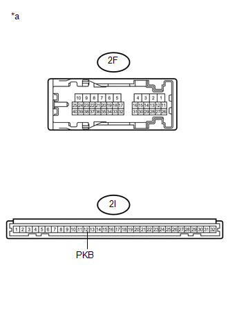
2F-22 - 2I-12 (PKB) |
Always |
Below 1 Ω |
|
2F-22 or 2I-12 (PKB) - Body ground |
Always |
10 kΩ or higher |
Text in Illustration
|
*a |
Component without harness connected (Instrument Panel Junction Block Assembly) |
| OK |
|
| NG |
|
REPLACE INSTRUMENT PANEL JUNCTION BLOCK ASSEMBLY |
|
|
|