| Last Modified: 08-28-2024 | 6.11:8.1.0 | Doc ID: RM100000000VKHJ |
| Model Year Start: 2016 | Model: Sienna | Prod Date Range: [12/2015 - 08/2016] |
| Title: LIGHTING (EXT): LIGHTING SYSTEM: Headlight Relay Circuit; 2016 MY Sienna [12/2015 - 08/2016] | ||
|
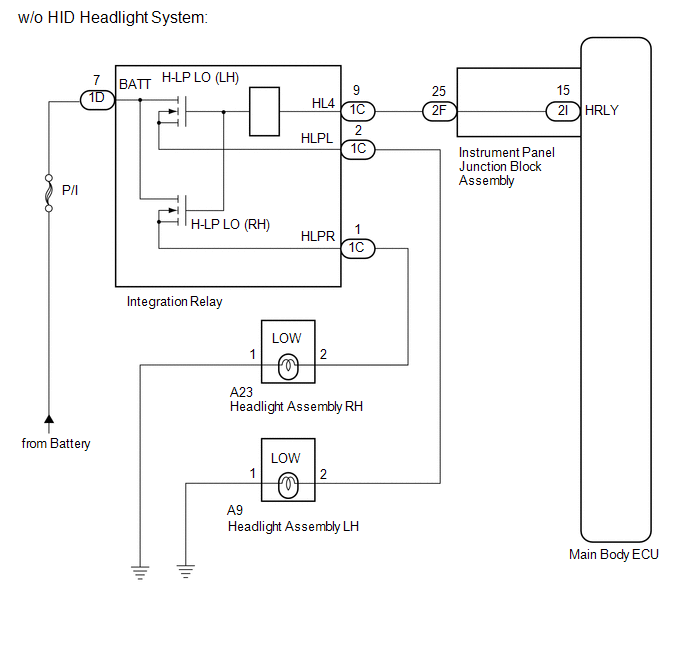
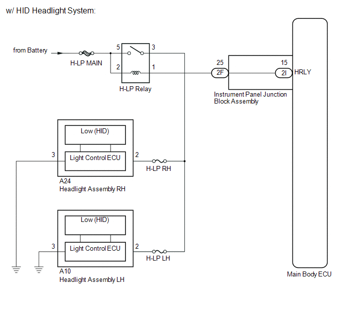
Headlight Relay Circuit |
DESCRIPTION
The main body ECU controls the integration relay*1 or headlight relay*2.
- *1: w/o HID Headlight System
- *2: w/ HID Headlight System
WIRING DIAGRAM
CAUTION / NOTICE / HINT
NOTICE:
Inspect the fuses for circuits related to this system before performing the following inspection procedure.
PROCEDURE
|
1. |
PERFORM ACTIVE TEST USING TECHSTREAM (HEADLIGHT RELAY) |
(a) Connect the Techstream to the DLC3.
(b) Turn the ignition switch to ON.
(c) Turn the Techstream on.
(d) Enter the following menus: Body Electrical / Main Body / Active Test.
(e) Check that the relays operate.
Main Body
|
Tester Display |
Test Part |
Control Range |
Diagnostic Note |
|---|---|---|---|
|
Headlight Relay |
Low beam headlight relay |
ON/OFF |
- |
OK:
Relays operates. (Low beam headlights illuminate.)
| OK |

|
PROCEED TO NEXT SUSPECTED AREA SHOWN IN PROBLEM SYMPTOMS TABLE |
|

|
2. |
SYSTEM CHECK |
(a) Check the vehicle specifications.
Result
|
Result |
Proceed to |
|---|---|
|
w/o HID Headlight System |
A |
|
w/ HID Headlight System |
B |
| B |
|
|
|
3. |
REPLACE INTEGRATION RELAY |
(a) Temporarily replace the integration relay with a new or normally functioning one.
|
|
4. |
PERFORM ACTIVE TEST USING TECHSTREAM (HEADLIGHT RELAY) |
(a) Connect the Techstream to the DLC3.
(b) Turn the ignition switch to ON.
(c) Turn the Techstream on.
(d) Enter the following menus: Body Electrical / Main Body / Active Test.
(e) Check that the relays operate.
Main Body
|
Tester Display |
Test Part |
Control Range |
Diagnostic Note |
|---|---|---|---|
|
Headlight Relay |
Low beam headlight relay |
ON/OFF |
- |
OK:
Headlight relays operate. (Low beam headlights illuminate.)
| OK |
|
END (INTEGRATION RELAY WAS DEFECTIVE) |
|
|
5. |
CHECK HARNESS AND CONNECTOR (BATTERY - INTEGRATION RELAY) |
|
(a) Disconnect the integration relay connector. |
|
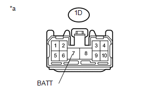
(b) Measure the voltage according to the value(s) in the table below.
Standard Voltage:
|
Tester Connector |
Condition |
Specified Condition |
|---|---|---|
|
1D-7 (BATT) - Body ground |
Always |
11 to 14 V |
Text in Illustration
|
*a |
Front view of wire harness connector (to Integration Relay) |
| NG |
|
REPAIR OR REPLACE HARNESS OR CONNECTOR |
|
|
6. |
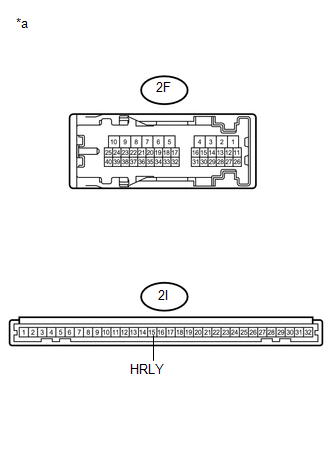
CHECK HARNESS AND CONNECTOR (INTEGRATION RELAY - INSTRUMENT PANEL JUNCTION BLOCK ASSEMBLY) |
(a) Disconnect the 1C integration relay connector.
(b) Disconnect the 2F instrument panel junction block assembly connector.
(c) Measure the resistance according to the value(s) in the table below.
Standard Resistance:
|
Tester Connection |
Condition |
Specified Condition |
|---|---|---|
|
1C-9 (HL4) - 2F-25 |
Always |
Below 1 Ω |
|
1C-9 (HL4) or 2F-25 - Body ground |
Always |
10 kΩ or higher |
| NG |
|
REPAIR OR REPLACE HARNESS OR CONNECTOR |
|
|
7. |
INSPECT INSTRUMENT PANEL JUNCTION BLOCK ASSEMBLY |
|
(a) Remove the instrument panel junction block assembly. |
|
(b) Measure the resistance according to the value(s) in the table below.
Standard Resistance:
|
Tester Connection |
Condition |
Specified Condition |
|---|---|---|
|
2F-25 - 2I-15 (HRLY) |
Always |
Below 1 Ω |
|
2F-25 or 2I-15 (HRLY) - Body ground |
Always |
10 kΩ or higher |
Text in Illustration
|
*a |
Component without harness connected (Instrument Panel Junction Block Assembly) |
| OK |
|
| NG |
|
REPLACE INSTRUMENT PANEL JUNCTION BLOCK ASSEMBLY |
|
8. |
INSPECT HEADLIGHT RELAY (H-LP RELAY) |
(a) Remove the headlight relay.
(b) Inspect the headlight relay (See page
![2016 MY Sienna [12/2015 - 08/2016]; LIGHTING (EXT): RELAY: ON-VEHICLE INSPECTION](/t3Portal/stylegraphics/info.gif) ).
).
| NG |
|
REPLACE HEADLIGHT RELAY |
|
|
9. |
CHECK HARNESS AND CONNECTOR (BATTERY - HEADLIGHT RELAY) |
(a) Remove the headlight relay.
(b) Measure the voltage according to the value(s) in the table below.
Standard Voltage:
|
Tester Connection |
Condition |
Specified Condition |
|---|---|---|
|
2 - Body ground |
Always |
11 to 14 V |
|
5 - Body ground |
Always |
11 to 14 V |
Text in Illustration
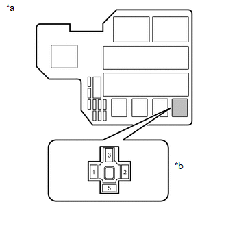
|
*a |
Engine Room Relay Block |
|
*b |
Headlight Relay Holder |
| NG |
|
REPAIR OR REPLACE HARNESS OR CONNECTOR |
|
|
10. |
CHECK HARNESS AND CONNECTOR (HEADLIGHT RELAY - INSTRUMENT PANEL JUNCTION BLOCK ASSEMBLY) |
(a) Disconnect the 2F instrument panel junction block assembly connector.
(b) Measure the resistance according to the value(s) in the table below.
Standard Resistance:
|
Tester Connection |
Condition |
Specified Condition |
|---|---|---|
|
1 - 2F-25 |
Always |
Below 1 Ω |
|
1 or 2F-25 - Body ground |
Always |
10 kΩ or higher |
| NG |
|
REPAIR OR REPLACE HARNESS OR CONNECTOR |
|
|
11. |
INSPECT INSTRUMENT PANEL JUNCTION BLOCK ASSEMBLY |
|
(a) Remove the instrument panel junction block assembly. |
|
(b) Measure the resistance according to the value(s) in the table below.
Standard Resistance:
|
Tester Connection |
Condition |
Specified Condition |
|---|---|---|
|
2F-25 - 2I-15 (HRLY) |
Always |
Below 1 Ω |
|
2F-25 or 2I-15 (HRLY) - Body ground |
Always |
10 kΩ or higher |
Text in Illustration
|
*a |
Component without harness connected (Instrument Panel Junction Block Assembly) |
| OK |
|
| NG |
|
REPLACE INSTRUMENT PANEL JUNCTION BLOCK ASSEMBLY |
|
|
|