- Malfunction in automatic light control sensor
- Open or short in automatic light control sensor circuit
| Last Modified: 08-28-2024 | 6.11:8.1.0 | Doc ID: RM100000000VKHH |
| Model Year Start: 2016 | Model: Sienna | Prod Date Range: [12/2015 - ] |
| Title: LIGHTING (EXT): LIGHTING SYSTEM: B1244; Light Sensor Circuit Malfunction; 2016 - 2020 MY Sienna [12/2015 - ] | ||
|
DTC |
B1244 |
Light Sensor Circuit Malfunction |
DESCRIPTION
The automatic light control sensor detects ambient light, converts it into an electrical signal, and outputs it to the main body ECU. The main body ECU turns on or off the headlights and taillights according to the signal.
|
DTC No. |
DTC Detecting Condition |
Trouble Area |
|---|---|---|
|
B1244 |
|
|
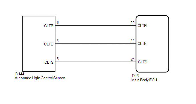
WIRING DIAGRAM
PROCEDURE
|
1. |
READ VALUE USING TECHSTREAM (ILLUMINATION RATE INFO) |
(a) Connect the Techstream to the DLC3.
(b) Turn the ignition switch to ON.
(c) Turn the Techstream on.
(d) Enter the following menus: Body Electrical / Main Body / Data List.
(e) Read the display on the Techstream.
Main Body
|
Tester Display |
Measurement Item/Range |
Normal Condition |
Diagnostic Note |
|---|---|---|---|
|
Illumination Rate Info |
Illumination rate information/0 ms to 99.99 ms |
Value is output according to ambient light levels |
- |
OK:
Normal condition listed above is displayed.
| OK |

|
|

|
2. |
CHECK HARNESS AND CONNECTOR (MAIN BODY ECU - AUTOMATIC LIGHT CONTROL SENSOR) |
(a) Disconnect the D144 automatic light control sensor connector.
(b) Disconnect the D13 main body ECU connector.
(c) Measure the resistance according to the value(s) in the table below.
Standard Resistance:
|
Tester Connection |
Condition |
Specified Condition |
|---|---|---|
|
D13-22 (CLTE) - D144-3 (CLTE) |
Always |
Below 1 Ω |
|
D13-21 (CLTS) - D144-5 (CLTS) |
Always |
Below 1 Ω |
|
D13-20 (CLTB) - D144-6 (CLTB) |
Always |
Below 1 Ω |
|
D13-22 (CLTE) or D144-3 (CLTE) - Body ground |
Always |
10 kΩ or higher |
|
D13-21 (CLTS) or D144-5 (CLTS) - Body ground |
Always |
10 kΩ or higher |
|
D13-20 (CLTB) or D144-6 (CLTB) - Body ground |
Always |
10 kΩ or higher |
| NG |
|
REPAIR OR REPLACE HARNESS OR CONNECTOR |
|
|
3. |
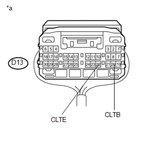
INSPECT MAIN BODY ECU |
(a) Reconnect the D13 main body ECU connector.
|
(b) Measure the voltage and resistance according to the value(s) in the table below. Standard Voltage:
Standard Resistance:
Text in Illustration
|
|
| NG |
|
|
|
4. |
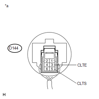
INSPECT AUTOMATIC LIGHT CONTROL SENSOR |
|
(a) Reconnect the automatic light control sensor connector. Text in Illustration
|
|
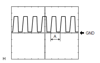
(b) Connect an oscilloscope to the automatic light control sensor connector.
|
(c) Check the waveform. OK:
HINT: If the ambient light becomes brighter, width A becomes narrower. |
|
| OK |
|
| NG |
|
|
|
|