| Last Modified: 08-28-2024 | 6.11:8.1.0 | Doc ID: RM100000000VKHF |
| Model Year Start: 2016 | Model: Sienna | Prod Date Range: [12/2015 - 11/2017] |
| Title: LIGHTING (EXT): LIGHTING SYSTEM: TERMINALS OF ECU; 2016 - 2017 MY Sienna [12/2015 - 11/2017] | ||
TERMINALS OF ECU
1. CHECK INSTRUMENT PANEL JUNCTION BLOCK ASSEMBLY AND MAIN BODY ECU
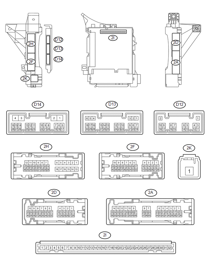
(a) Disconnect the 2A, 2D, 2F, 2K, D13 and D14 instrument panel junction block assembly and main body ECU connectors.
(b) Measure the voltage according to the value(s) in the table below.
|
Terminal No. (Symbol) |
Wiring Color |
Terminal Description |
Condition |
Specified Condition |
|---|---|---|---|---|
|
2A-17 - Body ground |
L - Body ground |
ACC power supply |
Ignition switch ACC |
11 to 14 V |
|
Ignition switch off |
Below 1 V |
|||
|
2A-16 - Body ground |
Y - Body ground |
IG power supply |
Ignition switch ON |
11 to 14 V |
|
Ignition switch off |
Below 1 V |
|||
|
2F-40 (BECU)*1 - Body ground |
W - Body ground |
Battery power supply |
Always |
11 to 14 V |
|
2K-1 - Body ground |
W - Body ground |
Battery power supply |
Always |
11 to 14 V |
- *1: w/o Smart Key System
If the result is not as specified, there may be a malfunction in the wire harness.
(c) Measure the resistance according to the value(s) in the table below.
|
Terminal No. (Symbol) |
Wiring Color |
Terminal Description |
Condition |
Specified Condition |
|---|---|---|---|---|
|
2D-28 (GND1) - Body ground |
W-B - Body ground |
Ground |
Always |
Below 1 Ω |
|
D14-3 (GND2) - Body ground |
W-B - Body ground |
Ground |
Always |
Below 1 Ω |
|
D13-22 (CLTE) - Body ground |
LG - Body ground |
Automatic light control ground |
Always |
Below 1 Ω |
If the result is not as specified, there may be a malfunction in the wire harness.
(d) Reconnect the 2A, 2D, 2F, 2K, D13 and D14 instrument panel junction block assembly and main body ECU connectors.
(e) Measure the voltage or check for pulses according to the value(s) in the table below.
|
Terminal No. (Symbol) |
Wiring Color |
Terminal Description |
Condition |
Specified Condition |
|---|---|---|---|---|
|
D13-15 (DRL)*2 - Body ground |
GR - Body ground |
Daytime running light system drive output |
Daytime running light system operates |
Below 1 V |
|
Daytime running light system does not operate |
11 to 14 V |
|||
|
2F-35 (DIM) - Body ground |
GR - Body ground |
High beam headlights drive output |
Dimmer switch in high or high flash position |
Below 1 V |
|
Dimmer switch in low position |
11 to 14 V |
|||
|
2F-22 (PKB) - Body ground |
R - Body ground |
Parking brake switch input |
Parking brake switch on |
Below 1 V |
|
Parking brake switch off |
11 to 14 V |
|||
|
2F-25 (HRLY) - Body ground |
LG - Body ground |
Headlight relay drive output |
Light control switch in head position |
Below 1 V |
|
Light control switch not in head position |
11 to 14 V |
|||
|
2H-34 (FLCY) - Body ground |
P - Body ground |
Front door courtesy light switch LH input |
Front door LH open |
Below 1 V |
|
Front door LH closed |
11 to 14 V |
|||
|
2H-36 (FRCY) - Body ground |
GR - Body ground |
Front door courtesy light switch RH input |
Front door RH open |
Below 1 V |
|
Front door RH closed |
11 to 14 V |
|||
|
2H-33 (LSWL) - Body ground |
LG - Body ground |
Rear door unlock detection switch LH input |
Rear door LH locked |
Pulse generation |
|
Rear door LH unlocked |
Below 1 V |
|||
|
D12-3 (LCTY) - Body ground |
GR - Body ground |
Rear door courtesy light switch LH input |
Rear door LH open |
Below 1 V |
|
Rear door LH closed |
Pulse generation |
|||
|
D13-5 (HU) - Body ground |
P - Body ground |
Dimmer switch high position signal input |
Dimmer switch in high or high flash position |
Below 1 V |
|
Dimmer switch in low position |
Pulse generation |
|||
|
D13-6 (RCTY) - Body ground |
L - Body ground |
Rear door courtesy light switch RH input |
Rear door RH open |
Below 1 V |
|
Rear door RH closed |
Pulse generation |
|||
|
D13-7 (LSFL) - Body ground |
V - Body ground |
Front door unlock detection switch LH input |
Front door LH locked |
Pulse generation |
|
Front door LH unlocked |
Below 1 V |
|||
|
D13-8 (HF) - Body ground |
SB - Body ground |
Dimmer switch high flash position signal input |
Dimmer switch in high flash position |
Below 1 V |
|
Dimmer switch not in high flash position |
Pulse generation |
|||
|
D13-18 (LSFR) - Body ground |
Y - Body ground |
Front door unlock detection RH switch input |
Front door RH locked |
Pulse generation |
|
Front door RH unlocked |
Below 1 V |
|||
|
D13-19 (BCTY) - Body ground |
GR - Body ground |
Back door courtesy light switch input |
Back door open |
Below 1 V |
|
Back door closed |
Pulse generation |
|||
|
D13-20 (CLTB) - Body ground |
R - Body ground |
Automatic light control sensor power supply output |
Ignition switch off |
Below 1 V |
|
Ignition switch ON and light control switch in AUTO position |
11 to 14 V |
|||
|
D13-21 (CLTS) - Body ground |
G - Body ground |
Automatic light control sensor signal input |
Ignition switch off |
Below 1 V |
|
Automatic light control system operates |
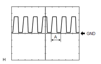
Pulse generation (See waveform 1) |
|||
|
D13-27 (FFOG) - Body ground |
R - Body ground |
Front fog light switch input |
Front fog light switch on |
Below 1 V |
|
Front fog light switch off |
Pulse generation |
|||
|
D13-28 (A) - Body ground |
V - Body ground |
Light control switch AUTO*3 or DRL*4 position signal input |
Light control switch in AUTO*3 or DRL*4 position |
Below 1 V |
|
Light control switch not in AUTO*3 or DRL*4 position |
Pulse generation |
|||
|
D13-29 (HEAD) - Body ground |
R - Body ground |
Light control switch head position input |
Light control switch in head position |
Below 1 V |
|
Light control switch not in head position and ignition switch off |
Pulse generation |
|||
|
Light control switch not in head position and ignition switch ON |
11 to 14 V |
|||
|
D13-30 (TAIL) - Body ground |
Y - Body ground |
Light control switch tail position signal input |
Light control switch in tail or head position |
Below 1 V |
|
Light control switch in neither tail nor head position, and ignition switch off |
Pulse generation |
|||
|
Light control switch in neither tail nor head position, and ignition switch ON |
11 to 14 V |
|||
|
D14-2 (LSWR) - Body ground |
L - Body ground |
Rear door unlock detection switch RH input |
Rear door RH locked |
Pulse generation |
|
Rear door RH unlocked |
Below 1 V |
- *2: w/ Daytime Running Light System
- *3: w/ Automatic Light Control System
- *4: w/ DRL switch
If the result is not as specified, the main body ECU or instrument panel junction block assembly may have a malfunction.
(1) Waveform 1
|
Item |
Content |
|---|---|
|
Tool setting |
5 V/DIV., 5 ms./DIV. |
HINT:
If the ambient light becomes brighter, width A becomes narrower.
2. CHECK HEADLIGHT SWIVEL ECU ASSEMBLY (w/ HID Headlight System)
(a) Disconnect the A45 headlight swivel ECU assembly connector.

(b) Measure the resistance according to the value(s) in the table below.
|
Terminal No. (Symbol) |
Wiring Color |
Terminal Description |
Condition |
Specified Condition |
|---|---|---|---|---|
|
A45-22 (E1) - Body ground |
W-B - Body ground |
Headlight swivel ECU assembly ground |
Always |
Below 1 Ω |
If the result is not as specified, there may be a malfunction in the wire harness.
(c) Measure the voltage according to the value(s) in the table below.
|
Terminal No. (Symbol) |
Wiring Color |
Terminal Description |
Condition |
Specified Condition |
|---|---|---|---|---|
|
A45-15 (IG) - Body ground |
G - Body ground |
Headlight swivel ECU assembly power supply |
Ignition switch off |
Below 1 V |
|
Ignition switch ON |
11 to 14 V |
If the result is not as specified, there may be a malfunction in the wire harness.
(d) Reconnect the A45 headlight swivel ECU assembly connector.
(e) Measure the voltage and check for pulses according to the value(s) in the table below.
|
Terminal No. (Symbol) |
Wiring Color |
Terminal Description |
Condition |
Specified Condition |
|---|---|---|---|---|
|
A45-7 (INIT) - A45-22 (E1) |
W - W-B |
Operation check signal |
Ignition switch ON, terminals LVL and GND of DLC3 connected |
Below 1 V |
|
Ignition switch ON, terminals LVL and GND of DLC3 not connected |
Approximately 5 V |
|||
|
A45-10 (SMR) - A45-22 (E1) |
V - W-B |
LIN communication |
Ignition switch off |
Below 1 V |
|
Ignition switch ON, inner rear view mirror connector disconnected |
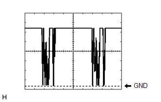
Pulse generation (See waveform 1) |
|||
|
A45-12 (CANH) - A45-22 (E1) |
G - W-B |
CAN communication |
Ignition switch off |
Below 1 V |
|
Ignition switch ON |
Pulse generation |
|||
|
A45-13 (CANL) - A45-22 (E1) |
W - W-B |
CAN communication |
Ignition switch off |
Below 1 V |
|
Ignition switch ON |
Pulse generation |
If the result is not as specified, the headlight swivel ECU assembly may have a malfunction.
(1) Waveform 1
|
Item |
Content |
|---|---|
|
Tool setting |
2 V/DIV., 20 ms./DIV. |
3. CHECK INNER REAR VIEW MIRROR ASSEMBLY (w/ HID Headlight System)
(a) Disconnect the T2 inner rear view mirror assembly connector.

(b) Measure the resistance according to the value(s) in the table below.
|
Terminal No. (Symbol) |
Wiring Color |
Terminal Description |
Condition |
Specified Condition |
|---|---|---|---|---|
|
T2-3 (E) - Body ground |
W-B - Body ground |
Inner rear view mirror assembly ground |
Always |
Below 1 Ω |
If the result is not as specified, there may be a malfunction in the wire harness.
(c) Measure the voltage according to the value(s) in the table below.
|
Terminal No. (Symbol) |
Wiring Color |
Terminal Description |
Condition |
Specified Condition |
|---|---|---|---|---|
|
T2-6 (IG) - Body ground |
L - Body ground |
Inner rear view mirror assembly power supply |
Ignition switch off |
Below 1 V |
|
Ignition switch ON |
11 to 14 V |
If the result is not as specified, there may be a malfunction in the wire harness.
(d) Reconnect the T2 inner rear view mirror assembly connector.
(e) Measure the voltage or check for pulses according to the value(s) in the table below.
|
Terminal No. (Symbol) |
Wiring Color |
Terminal Description |
Condition |
Specified Condition |
|---|---|---|---|---|
|
T2-12 (LIN) - T2-3 (E) |
V - W-B |
LIN communication |
Ignition switch off |
Below 1 V |
|
Automatic high beam system operates |
Pulse generation (See waveform 1) |
If the result is not as specified, the inner rear view mirror assembly may have a malfunction.
(1) Waveform 1
|
Item |
Content |
|---|---|
|
Tool setting |
2 V/DIV., 20 ms./DIV. |
4. CHECK COMBINATION METER ASSEMBLY
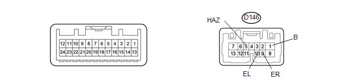
(a) Disconnect the D146 combination meter assembly connector.
(b) Measure the voltage according to the value(s) in the table below.
|
Terminal No. (Symbol) |
Wiring Color |
Terminal Description |
Condition |
Specified Condition |
|---|---|---|---|---|
|
D146-1 (B) - Body ground |
W - Body ground |
Battery power supply |
Always |
11 to 14 V |
If the result is not as specified, there may be a malfunction in the wire harness.
(c) Reconnect the D146 combination meter assembly connector.
(d) Measure the voltage according to the value(s) in the table below.
|
Terminal No. (Symbol) |
Wiring Color |
Terminal Description |
Condition |
Specified Condition |
|---|---|---|---|---|
|
D146-5 (HAZ) - Body ground |
B - Body ground |
Hazard warning signal switch input |
Hazard warning signal switch off |
11 to 14 V |
|
Hazard warning signal switch on |
Below 1 V |
|||
|
D146-9 (ER) - Body ground |
GR - Body ground |
Turn signal switch right signal input |
Ignition switch ON, turn signal switch in neutral position |
11 to 14 V |
|
Ignition switch ON, turn signal switch in right turn position |
Below 1 V |
|||
|
D146-10 (EL) - Body ground |
V - Body ground |
Turn signal switch left signal input |
Ignition switch ON, turn signal switch in neutral position |
11 to 14 V |
|
Ignition switch ON, turn signal switch in left turn position |
Below 1 V |
If the result is not as specified, the combination meter assembly may be malfunctioning.
|
|
|