| Last Modified: 08-28-2024 | 6.11:8.1.0 | Doc ID: RM100000000VKET |
| Model Year Start: 2016 | Model: Sienna | Prod Date Range: [12/2015 - ] |
| Title: WIPER / WASHER: WIPER AND WASHER SYSTEM(w/ Rain Sensor): Wiper and Washer Switch Circuit; 2016 - 2020 MY Sienna [12/2015 - ] | ||
|
Wiper and Washer Switch Circuit |
DESCRIPTION
This circuit detects the state of the windshield wiper switch assembly (front wiper switch and front washer switch) and sends it to the windshield wiper relay assembly.
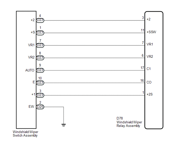
WIRING DIAGRAM
PROCEDURE
|
1. |
INSPECT WINDSHIELD WIPER SWITCH ASSEMBLY |
|
(a) Remove the windshield wiper switch assembly (See page
|
|
![2016 - 2020 MY Sienna [12/2015 - ]; WIPER / WASHER: WIPER SWITCH: REMOVAL](/t3Portal/stylegraphics/info.gif)
(b) Measure the resistance according to the value(s) in the table below.
Standard Resistance:
Front Wiper Switch
|
Tester Connection |
Switch Condition |
Specified Condition |
|---|---|---|
|
D23-3 (+1) - D23-1 (+S) |
OFF |
Below 1 Ω |
|
D23-3 (+1) - D23-2 (+B) |
MIST |
|
|
LO |
||
|
D23-2 (+B) - D23-4 (+2) |
HI |
|
|
D23-9 (AUTO) - D23-10 (E) |
AUTO |
|
|
D23-3 (+1) - D23-1 (+S) |
Front Washer Switch
|
Tester Connection |
Switch Condition |
Specified Condition |
|---|---|---|
|
D25-2 (EW) - D25-3 (WF) |
ON |
Below 1 Ω |
|
OFF |
10 kΩ or higher |
Adjusting Ring*1
|
Tester Connection |
Condition |
Specified Condition |
|---|---|---|
|
D23-7 (VR1) - D23-8 (VR2) |
Adjusting ring changed from (+) side to (-) side |
0 to 2.7 kΩ |
HINT:
*1: The rain sensor sensitivity can be adjusted by the windshield wiper switch adjusting ring.
Text in Illustration
|
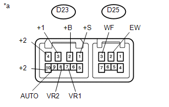
*a |
Component without harness connected (Windshield Wiper Switch Assembly) |
| NG |

|
|

|
2. |
CHECK HARNESS AND CONNECTOR (WIPER SWITCH - WIPER RELAY AND BODY GROUND) |
(a) Disconnect the D23 and D25 windshield wiper switch assembly connectors.
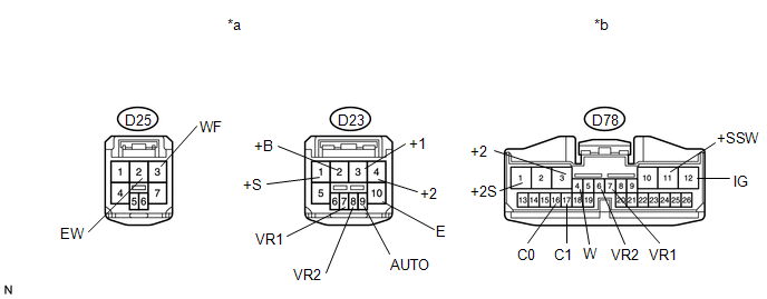
Text in Illustration
|
*a |
Front view of wire harness connector (to Windshield Wiper Switch Assembly) |
*b |
Front view of wire harness connector (to Windshield Wiper Relay Assembly) |
(b) Disconnect the D78 windshield wiper relay assembly connector.
(c) Measure the resistance according to the value(s) in the table below.
Standard Resistance:
|
Tester Connection |
Condition |
Specified Condition |
|---|---|---|
|
D23-3 (+1) - D78-1 (+2S) |
Always |
Below 1 Ω |
|
D23-3 (+1) - Body ground |
Always |
10 kΩ or higher |
|
D23-4 (+2) - D78-3 (+2) |
Always |
Below 1 Ω |
|
D23-4 (+2) - Body ground |
Always |
10 kΩ or higher |
|
D23-1 (+S) - D78-11 (+SSW) |
Always |
Below 1 Ω |
|
D23-1 (+S) - Body ground |
Always |
10 kΩ or higher |
|
D23-9 (AUTO) - D78-17 (C1) |
Always |
Below 1 Ω |
|
D23-9 (AUTO) - Body ground |
Always |
10 kΩ or higher |
|
D23-10 (E) - D78-16 (C0) |
Always |
Below 1 Ω |
|
D23-10 (E) - Body ground |
Always |
10 kΩ or higher |
|
D23-7 (VR1) - D78-7 (VR1) |
Always |
Below 1 Ω |
|
D23-7 (VR1) - Body ground |
Always |
10 kΩ or higher |
|
D23-8 (VR2) - D78-6 (VR2) |
Always |
Below 1 Ω |
|
D23-8 (VR2) - Body ground |
Always |
10 kΩ or higher |
|
D25-2 (EW) - Body ground |
Always |
Below 1 Ω |
| OK |
|
PROCEED TO NEXT SUSPECTED AREA SHOWN IN PROBLEM SYMPTOMS TABLE |
| NG |
|
REPAIR OR REPLACE HARNESS OR CONNECTOR |
|
|
|