- Connect a positive (+) battery lead to terminal 2 (B), connect a negative (-) battery lead to terminal 1 (GND), and keep them connected for 3 seconds or more.
- With terminals 2 (B) and 1 (GND) connected, connect a negative (-) battery lead to terminal 10 (UP).
- Disconnect and reconnect a negative (-) battery lead to terminal 10 (UP) within 1 second.
| Last Modified: 08-28-2024 | 6.11:8.1.0 | Doc ID: RM100000000VK6U |
| Model Year Start: 2016 | Model: Sienna | Prod Date Range: [12/2015 - ] |
| Title: WINDOW / GLASS: POWER WINDOW REGULATOR MOTOR(for Front Door): INSPECTION; 2016 - 2020 MY Sienna [12/2015 - ] | ||
INSPECTION
PROCEDURE
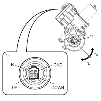
1. INSPECT POWER WINDOW REGULATOR MOTOR ASSEMBLY LH
|
(a) Apply positive (+) battery voltage to connector terminal 2 (B). Text in Illustration
NOTICE: Do not apply positive (+) battery voltage to any terminals other than terminal 2 (B) to avoid damaging the pulse sensor inside the motor. |
|
(b) Connect a ground lead to connector terminals 1 (GND) and 7 (DOWN) or 10 (UP).
(c) Check that the motor gear rotates smoothly as follows:
OK:
|
Measurement Condition |
Specified Condition |
|---|---|
|
|
Motor gear rotates clockwise |
|
Motor gear rotates counterclockwise |
- If the result is not as specified, replace the power window regulator motor assembly LH.
CAUTION:
Reset the power window regulator motor (initialize the pulse sensor) after installing the power window regulator motor and regulator onto the door.
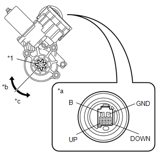
2. INSPECT POWER WINDOW REGULATOR MOTOR ASSEMBLY RH
|
(a) Apply positive (+) battery voltage to connector terminal 2 (B). Text in Illustration
NOTICE: Do not apply positive (+) battery voltage to any terminals other than terminal 2 (B) to avoid damaging the pulse sensor inside the motor. |
|
(b) Connect a ground lead to connector terminals 1 (GND) and 7 (DOWN) or 10 (UP).
(c) Check that the motor gear rotates smoothly as follows:
OK:
|
Measurement Condition |
Specified Condition |
|---|---|
|
Motor gear rotates counterclockwise |
|
Motor gear rotates clockwise |
- If the result is not as specified, replace the power window regulator motor assembly RH.
CAUTION:
Reset the power window regulator motor (initialize the pulse sensor) after installing the power window regulator motor and regulator onto the door.
|
|
|

