| Last Modified: 08-28-2024 | 6.11:8.1.0 | Doc ID: RM100000000VK1M |
| Model Year Start: 2016 | Model: Sienna | Prod Date Range: [12/2015 - 08/2016] |
| Title: HEATING / AIR CONDITIONING: AIR CONDITIONING SYSTEM: Air Conditioning Compressor Magnetic Clutch Circuit; 2016 MY Sienna [12/2015 - 08/2016] | ||
|
Air Conditioning Compressor Magnetic Clutch Circuit |
DESCRIPTION
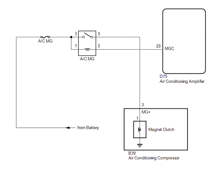
When the air conditioning amplifier is turned on, a magnet clutch ON signal is sent from the MGC terminal of the air conditioning amplifier. Then, the magnet-clutch relay (A/C MG relay) turns on to operate the magnet clutch.
WIRING DIAGRAM
CAUTION / NOTICE / HINT
NOTICE:
Inspect the fuses for circuits related to this system before performing the following inspection.
PROCEDURE
|
1. |
CHECK CAN COMMUNICATION SYSTEM |
(a) Connect the Techstream to the DLC3.
(b) Turn the ignition switch to ON.
(c) Turn the Techstream on.
(d) Select "Communication Bus Check"
OK:
All ECUs and sensors connected to the CAN communication system are displayed.
| NG |

|
|
|
2. |
PERFORM ACTIVE TEST USING TECHSTREAM (MAGNETIC CLUTCH RELAY) |
(a) Connect the Techstream to the DLC3.
(b) Turn the ignition switch to ON.
(c) Turn the Techstream on.
(d) Enter the following menus: Body Electrical / Air Conditioner / Active Test.
(e) Check that the relays operate.
Air Conditioner
|
Tester Display |
Test Part |
Control Range |
Diagnostic Note |
|---|---|---|---|
|
Magnetic Clutch Relay |
A/C compressor |
OFF, ON |
- |
OK:
The magnet clutch operates normally.
| NG |

|
|
|
3. |
READ VALUE USING TECHSTREAM (A/C SIGNAL) |
(a) Connect the Techstream to the DLC3.
(b) Turn the ignition switch to ON.
(c) Turn the Techstream on.
(d) Enter the following menus: Powertrain / Engine / Data List.
(e) Check the value(s) by referring to the table below.
Engine
|
Tester Display |
Measurement Item/Range |
Normal Condition |
Diagnostic Note |
|---|---|---|---|
|
A/C Signal |
A/C Signal / ON, OFF |
ON: A/C ON OFF: A/C OFF |
- |
OK:
The display is as specified in the normal condition.
| OK |

|
PROCEED TO NEXT SUSPECTED AREA SHOWN IN PROBLEM SYMPTOMS TABLE |
| NG |

|
|
4. |
INSPECT MAGNET-CLUTCH RELAY (A/C MG RELAY) |
(a) Remove the magnet-clutch relay (A/C MG relay).
(b) Inspect the magnet-clutch relay (A/C MG relay) (See page
![2016 - 2020 MY Sienna [12/2015 - ]; HEATING / AIR CONDITIONING: RELAY: ON-VEHICLE INSPECTION](/t3Portal/stylegraphics/info.gif) ).
).
| NG |

|
REPLACE MAGNET-CLUTCH RELAY (A/C MG RELAY) |
|
|
5. |
CHECK HARNESS AND CONNECTOR (MGC CIRCUIT) |
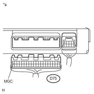
(a) Disconnect the air conditioning amplifier connector.
(b) Measure the voltage according to the value(s) in the table below.
Standard Voltage:
|
Tester Connection |
Condition |
Specified Condition |
|---|---|---|
|
D75-20 (MGC) - Body ground |
Always |
11 to 14 V |
Text in Illustration
|
*a |
Rear view of wire harness connector (to Air Conditioning Amplifier) |
| NG |

|
|
|
6. |
INSPECT AIR CONDITIONING AMPLIFIER (MGC VOLTAGE) |
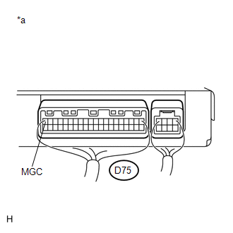
(a) Remove the air conditioning amplifier with its connectors still connected (See page
![2016 - 2020 MY Sienna [12/2015 - ]; HEATING / AIR CONDITIONING: AIR CONDITIONING AMPLIFIER: REMOVAL](/t3Portal/stylegraphics/info.gif) ).
).
(b) Measure the voltage according to the value(s) in the table below.
Standard Voltage:
|
Tester Connection |
Switch Condition |
Specified Condition |
|---|---|---|
|
D75-20 (MGC) - Body ground |
Engine running and A/C switch on |
Below 1 V |
|
Engine running and A/C switch off |
11 to 14 V |
Text in Illustration
|
*a |
Component with harness connected (Air Conditioning Amplifier) |
| NG |

|
|
|
7. |
INSPECT AIR CONDITIONING COMPRESSOR (COMPRESSOR HARNESS) |
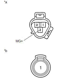
(a) Disconnect the air conditioning compressor connector.
(b) Disconnect the magnet clutch connector.
(c) Measure the resistance according to the value(s) in the table below.
Standard Resistance:
|
Tester Connection |
Condition |
Specified Condition |
|---|---|---|
|
3 (MG+) - 1 |
Always |
Below 1 Ω |
|
3 (MG+) - Body ground |
Always |
10 kΩ or higher |
Text in Illustration
|
*a |
Component without harness connected (Air Conditioning Compressor) |
|
*b |
Component without harness connected (Magnet Clutch) |
| NG |

|
|
|
8. |
INSPECT MAGNET CLUTCH |
|
(a) Measure the resistance according to the value(s) in the table below. Standard Resistance:
Text in Illustration
|
|
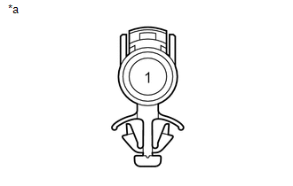
(b) When connector terminal 1 is connected to the positive (+) battery terminal, check that the following occurs: 1) the magnet clutch operating sound can be heard, and 2) the magnet clutch hub and rotor lock.
| NG |

|
|
|
9. |
CHECK HARNESS AND CONNECTOR (AIR CONDITIONING COMPRESSOR - MAGNET-CLUTCH RELAY) |
(a) Disconnect the B39 air conditioning compressor connector.
(b) Remove the magnet-clutch relay (MG CLT relay).
(c) Measure the resistance according to the value(s) in the table below.
Standard Resistance:
|
Tester Connection |
Condition |
Specified Condition |
|---|---|---|
|
B39-3 (MG+) - A/C MG relay holder 5 |
Always |
Below 1 Ω |
|
B39-3 (MG+) or A/C MG relay holder 5 - Body ground |
Always |
10 kΩ or higher |
| OK |

|
| NG |

|
REPAIR OR REPLACE HARNESS OR CONNECTOR |
|
10. |
CHECK HARNESS AND CONNECTOR (MAGNET-CLUTCH RELAY - BATTERY) |
|
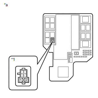
(a) Remove the magnet-clutch relay (A/C MG relay). |
|
(b) Measure the voltage according to the value(s) in the table below.
Standard Voltage:
|
Tester Connection |
Condition |
Specified Condition |
|---|---|---|
|
A/C MG relay holder 1 - Body ground |
Always |
11 to 14 V |
|
A/C MG relay holder 3 - Body ground |
Always |
11 to 14 V |
Text in Illustration
|
*1 |
Magnet-clutch Relay (A/C MG Relay) Holder |
|
*a |
Component without relay installed (Engine Room Relay Block) |
| OK |

|
REPAIR OR REPLACE HARNESS OR CONNECTOR (AIR CONDITIONING AMPLIFIER - MAGNET-CLUTCH RELAY) |
| NG |

|
REPAIR OR REPLACE HARNESS OR CONNECTOR |
|
11. |
REPLACE AIR CONDITIONING AMPLIFIER |
(a) Replace the air conditioning amplifier with a normal one (See page
![2016 - 2020 MY Sienna [12/2015 - ]; HEATING / AIR CONDITIONING: AIR CONDITIONING AMPLIFIER: REMOVAL](/t3Portal/stylegraphics/info.gif) ).
).
(b) Check that the condition returns to normal.
OK:
Same problem does not occur.
| OK |

|
END (AIR CONDITIONING AMPLIFIER WAS DEFECTIVE) |
| NG |

|
|
|
|

