- Air conditioner pressure sensor
- Harness or connector between air conditioner pressure sensor and air conditioning amplifier
- Air conditioning amplifier
| Last Modified: 08-28-2024 | 6.11:8.1.0 | Doc ID: RM100000000VK11 |
| Model Year Start: 2016 | Model: Sienna | Prod Date Range: [12/2015 - 08/2016] |
| Title: HEATING / AIR CONDITIONING: AIR CONDITIONING SYSTEM: B1423/23; Pressure Sensor Circuit; 2016 MY Sienna [12/2015 - 08/2016] | ||
|
DTC |
B1423/23 |
Pressure Sensor Circuit |
DESCRIPTION
This DTC is output when the refrigerant pressure is either extremely low (190 kPa [2.0 kgf/cm2, 28 psi] or less) or extremely high (3140 kPa [32.0 kgf/cm2, 455 psi] or more). The air conditioning pressure sensor, which is installed on the pipe of the high pressure side, detects the refrigerant pressure and sends refrigerant pressure signals to the air conditioning amplifier. The air conditioning amplifier determines the pressure from the signals in accordance with the sensor characteristics, and controls the compressor accordingly.
|
DTC Code |
DTC Detection Condition |
Trouble Area |
|---|---|---|
|
B1423/23 |
Open or short in air conditioning pressure sensor circuit |
|
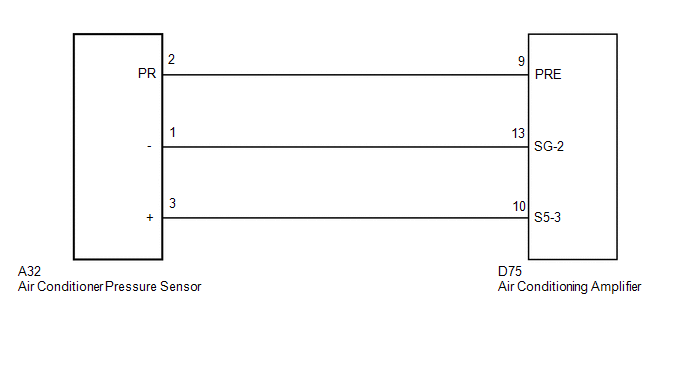
WIRING DIAGRAM
PROCEDURE
|
1. |
CHECK REFRIGERANT PRESSURE |
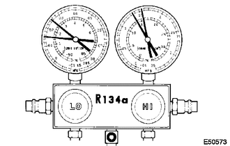
(a) Install the manifold gauge set (See page
![2016 - 2020 MY Sienna [12/2015 - ]; HEATING / AIR CONDITIONING: REFRIGERANT: ON-VEHICLE INSPECTION](/t3Portal/stylegraphics/info.gif) ).
).
(b) Read the manifold gauge pressure when the following conditions are established.
(1) Prepare the vehicle in accordance with the chart below.
|
Item |
Condition |
|---|---|
|
Engine speed |
1500 rpm |
|
Vehicle doors |
Fully open |
|
Temperature setting |
MAX COLD |
|
Blower speed |
HI |
|
A/C switch |
ON |
|
Air inlet |
RECIRC |
(2) When the refrigerant volume is correct, the gauge reading indicates as follows:
Standard:
|
Tester Connection |
Refrigerant Pressure |
|---|---|
|
Low pressure side |
150 to 250 kPa (1.5 to 2.5 kg/cm2, 22 to 36 psi) |
|
High pressure side |
1370 to 1570 kPa (14.0 to 16.0 kg/cm2, 199 to 228 psi) |
HINT:
Pressure varies in accordance with certain conditions such as outside air temperature, sunlight and wind.
| NG |

|
|

|
2. |
READ VALUE USING TECHSTREAM (REG PRESS SENS) |
(a) Connect Techstream to the DLC3.
(b) Turn the ignition switch to ON.
(c) Turn the Techstream on.
(d) Enter the following menus: Body Electrical / Air Conditioner / Data List.
(e) Check the value(s) by referring to the table below.
Air Conditioner
|
Tester Display |
Measurement Item/Range |
Normal Condition |
Diagnostic Note |
|---|---|---|---|
|
Regulator Pressure Sensor |
Air conditioner pressure sensor/ Min.: -66.22 psi (gauge) Max.: 477.68 psi (gauge) |
Actual regulator pressure displayed |
- |
OK:
The display is as specified in the normal condition column.
Result
|
Result |
Proceed to |
|---|---|
|
NG |
A |
|
OK (When troubleshooting according to Problem Symptoms Table) |
B |
|
OK (When troubleshooting according to the DTC) |
C |
| B |
|
PROCEED TO NEXT SUSPECTED AREA SHOWN IN PROBLEM SYMPTOMS TABLE |
| C |
|
|
|
3. |
CHECK HARNESS AND CONNECTOR (AIR CONDITIONER PRESSURE SENSOR - AIR CONDITIONING AMPLIFIER) |
(a) Disconnect the air conditioner pressure sensor connector.
(b) Disconnect the air conditioning amplifier connector.
(c) Measure the resistance according to the value(s) in the table below.
Standard Resistance:
|
Tester Connection |
Condition |
Specified Condition |
|---|---|---|
|
A32-3 (+) - D75-10 (S5-3) |
Always |
Below 1 Ω |
|
A32-2 (PR) - D75-9 (PRE) |
Always |
Below 1 Ω |
|
A32-1 (-) - D75-13 (SG-2) |
Always |
Below 1 Ω |
|
A32-3 (+) - Body ground |
Always |
10 kΩ or higher |
|
A32-2 (PR) - Body ground |
Always |
10 kΩ or higher |
|
A32-1 (-) - Body ground |
Always |
10 kΩ or higher |
| NG |
|
REPAIR OR REPLACE HARNESS OR CONNECTOR |
|
|
4. |
INSPECT AIR CONDITIONING AMPLIFIER |
|
(a) Remove the air conditioning amplifier with its connectors still connected. |
|
(b) Measure the resistance according to the value(s) in the table below.
Standard Resistance:
|
Tester Connection |
Condition |
Specified Condition |
|---|---|---|
|
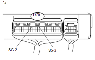
D75-13 (SG-2) - Body ground |
Always |
Below 1 Ω |
Text in Illustration
|
*a |
Component with harness connected (Air Conditioning Amplifier) |
(c) Turn the ignition switch to ON.
(d) Measure the voltage according to the value(s) in the table below.
Standard Voltage:
|
Tester Connection |
Switch Condition |
Specified Condition |
|---|---|---|
|
D75-10 (S5-3) - D75-13 (SG-2) |
Ignition switch ON (A/C ON) |
4.75 to 5.25 V |
| NG |
|
|
|
5. |
INSPECT AIR CONDITIONER PRESSURE SENSOR |
|
(a) Remove the air conditioning amplifier with its connectors still connected. |
|
(b) Set the manifold gauge.
(c) Warm up the engine.
(d) Turn the A/C switch ON.
(e) Measure the voltage according to the value(s) in the table below.
Standard Voltage:
|
Tester Connection |
Refrigerant Pressure |
Specified Condition |
|---|---|---|
|
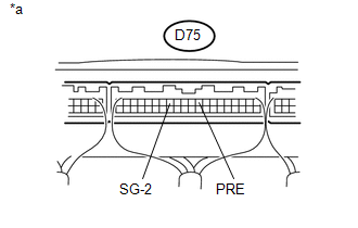
D75-9 (PRE) - D75-13 (SG-2) |
176 to 3025 kPa (1.8 to 30.9 kgf/cm2, 26 to 438 psi) |
0.63 to 4.72 V |
Text in Illustration
|
*a |
Component without harness connected (Air Conditioning Amplifier) |
| OK |
|
| NG |
|
|
|
|