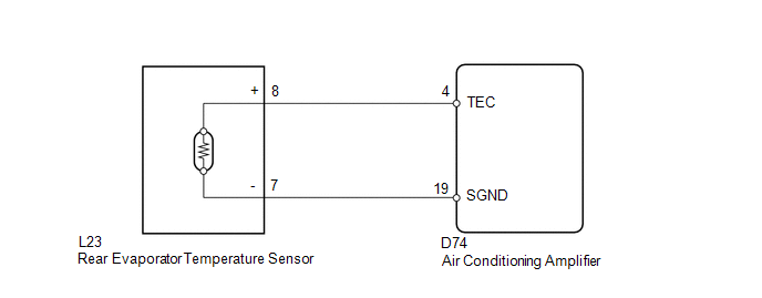
- Rear evaporator temperature sensor
- Harness or connector between rear evaporator temperature sensor and air conditioning amplifier
- Air conditioning amplifier
| Last Modified: 08-28-2024 | 6.11:8.1.0 | Doc ID: RM100000000VK0Z |
| Model Year Start: 2016 | Model: Sienna | Prod Date Range: [12/2015 - 08/2016] |
| Title: HEATING / AIR CONDITIONING: AIR CONDITIONING SYSTEM: B1417/17; Rear Evaporator Temperature Sensor Circuit; 2016 MY Sienna [12/2015 - 08/2016] | ||
|
DTC |
B1417/17 |
Rear Evaporator Temperature Sensor Circuit |
DESCRIPTION
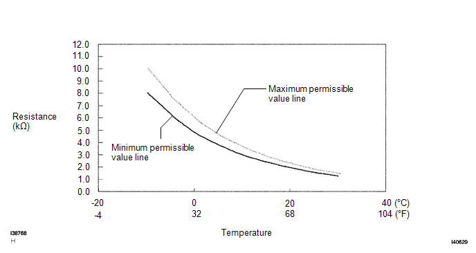
The rear evaporator temperature sensor is installed on the rear evaporator. It detects the rear evaporator temperature. The sensor sends a signal to the air conditioning amplifier. The resistance of the rear evaporator temperature sensor changes in accordance with the rear evaporator temperature. As the temperature decreases, the resistance increases. As the temperature increases, the resistance decreases.
The air conditioning amplifier applies voltage (5 V) to the rear evaporator temperature sensor and reads voltage changes as the resistance of the rear evaporator temperature sensor changes.
|
DTC Code |
DTC Detection Condition |
Trouble Area |
|---|---|---|
|
B1417/17 |
Open or short in rear evaporator temperature sensor circuit |
|
WIRING DIAGRAM
PROCEDURE
|
1. |
READ VALUE USING TECHSTREAM |
(a) Connect Techstream to the DLC3.
(b) Turn the ignition switch to ON.
(c) Turn the Techstream on.
(d) Enter the following menus: Body Electrical / Air Conditioner / Data List.
(e) Check the value(s) by referring to the table below.
Air Conditioner
|
Tester Display |
Measurement Item/Range |
Normal Condition |
Diagnostic Note |
|---|---|---|---|
|
Ambient Temp Sens (Rear) |
Rear evaporator temperature sensor / Min.: -29.7°C (-21.46°F) Max.: 59.55°C (139.19°F) |
Actual rear evaporator temperature is displayed |
Open in the circuit: -29.7°C (- 21.46°F) Short in the circuit: 59.55°C (139.19°F) |
OK:
The display is as specified in the normal condition column.
Result
|
Result |
Proceed to |
|---|---|
|
NG |
A |
|
OK (When troubleshooting according to the PROBLEM SYMPTOMS TABLE) |
B |
|
OK (When troubleshooting according to the DTC) |
C |
| B |

|
PROCEED TO NEXT SUSPECTED AREA SHOWN IN PROBLEM SYMPTOMS TABLE |
| C |
|
|

|
2. |
INSPECT REAR EVAPORATOR TEMPERATURE SENSOR |
|
(a) Remove the rear evaporator temperature sensor. |
|
(b) Measure the resistance according to the value(s) in the table below.
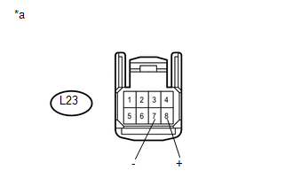
Text in Illustration
|
*a |
Front view of wire harness connector (to Rear Evaporator Temperature Sensor) |
Standard Resistance:
|
Tester Connection |
Condition |
Specified Condition |
|---|---|---|
|
L23-7 (-) - L23-8 (+) |
-10°C (14°F) |
7.40 to 9.20 kΩ |
|
L23-7 (-) - L23-8 (+) |
-5°C (23°F) |
5.65 to 7.00 kΩ |
|
L23-7 (-) - L23-8 (+) |
0°C (32°F) |
4.35 to 5.40 kΩ |
|
L23-7 (-) - L23-8 (+) |
5°C (41°F) |
3.40 to 4.20 kΩ |
|
L23-7 (-) - L23-8 (+) |
10°C (50°F) |
2.68 to 3.30 kΩ |
|
L23-7 (-) - L23-8 (+) |
15°C (59°F) |
2.10 to 2.60 kΩ |
|
L23-7 (-) - L23-8 (+) |
20°C (68°F) |
1.66 to 2.10 kΩ |
|
L23-7 (-) - L23-8 (+) |
25°C (77°F) |
1.32 to 1.66 kΩ |
|
L23-7 (-) - L23-8 (+) |
30°C (86°F) |
1.05 to 1.35 kΩ |
NOTICE:
- Even slightly touching the sensor may change the resistance value. Be sure to hold the connector of the sensor.
- When measuring, the sensor temperature must be the same as the rear evaporator temperature.
HINT:
As the temperature increases, the resistance decreases (see the graph).
| NG |
|
|
|
3. |
CHECK HARNESS AND CONNECTOR (REAR EVAPORATOR TEMPERATURE SENSOR - AIR CONDITIONING AMPLIFIER) |
(a) Disconnect the rear evaporator temperature sensor connector.
(b) Disconnect the air conditioning amplifier connector.
(c) Measure the resistance according to the value(s) in the table below.
Standard Resistance:
|
Tester Connection |
Condition |
Specified Condition |
|---|---|---|
|
L23-8 (+) - D74-4 (TEC) |
Always |
Below 1 Ω |
|
L23-7 (-) - D74-19 (SGND) |
Always |
Below 1 Ω |
|
D74-4 (TEC) - Body ground |
Always |
10 kΩ or higher |
|
D74-19 (SGND) - Body ground |
Always |
10 kΩ or higher |
| OK |
|
| NG |
|
REPAIR OR REPLACE HARNESS OR CONNECTOR |
|
|
|