- No right swivel operation
- No left swivel operation
| Last Modified: 08-28-2024 | 6.11:8.1.0 | Doc ID: RM100000000VJUL |
| Model Year Start: 2016 | Model: Sienna | Prod Date Range: [12/2015 - ] |
| Title: SEAT: AUTO ACCESS SEAT SYSTEM: DIAGNOSIS SYSTEM; 2016 - 2020 MY Sienna [12/2015 - ] | ||
DIAGNOSIS SYSTEM
1. SERVICE OPERATION MODE
HINT:
-
Buzzer pattern (See page
![2016 - 2020 MY Sienna [12/2015 - ]; SEAT: AUTO ACCESS SEAT SYSTEM: SYSTEM DESCRIPTION](/t3Portal/stylegraphics/info.gif) ).
).
- Auto access seat position information is stored in EEPROM (Electronically Erasable Programmable Read Only Memory). Position information is initialized in service operation mode.
-
Service operation mode allows diagnostic codes stored in the RAM of the position control ECU assembly to be output/cleared, and enables initialization of the auto access seat position information stored in EEPROM.
Memory
Operation
RAM
Output diagnostic codes
RAM
Clear diagnostic codes
EEPROM
Initialize auto access seat position information
(a) Service operation mode flowchart.
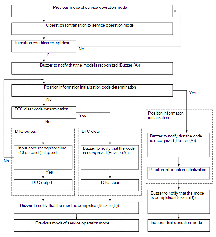
HINT:
- After entering service operation mode, regardless of the switch positions, service operation mode will run until completed.
- If only 1 code is entered, or if the code cannot be determined, diagnostic codes stored in RAM will be output.
- If unstable power source voltage is detected, the system will not enter service operation mode.
(b) Operation to enter service operation mode.
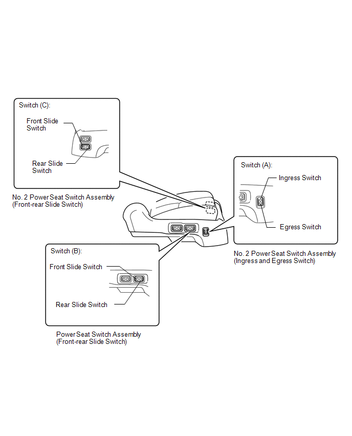
(1) Press and hold the ingress switch or egress switch of switch (A).
(2) With switch (A) depressed, press and hold the front slide switch or rear slide switch of switch (B) or (C) for 10 seconds to enter service operation mode, and confirm that buzzer (A) sounds.
(c) Conditions for ending service operation mode.
(1) If any of the conditions below are met, service operation mode will end.
|
Condition |
|---|
|
Diagnostic code output complete |
|
Diagnostic code clear complete |
|
Auto access seat position information initialization complete |
(d) Conditions for cancelling service operation mode.
(1) If the condition below is met, service operation mode will be cancelled.
|
Condition |
|---|
|
Unstable power supply voltage detected |
(e) Diagnostic code output.

(1) Press and hold the ingress switch or egress switch of switch (A).
(2) With switch (A) depressed, press and hold the front slide switch or rear slide switch of switch (B) or (C) for 10 seconds to enter service operation mode, and confirm that buzzer (A) sounds.
(3) After buzzer (A) sounds, turn all operated switches to off.
(4) 10 seconds after all operated switches are turned off, the diagnostic codes are output by sounding the buzzer (M).
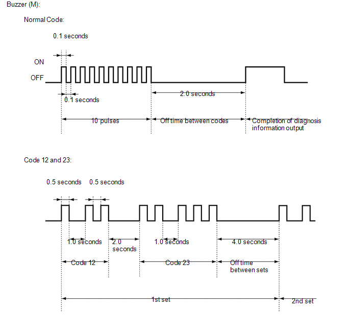
HINT:
- If there is no diagnostic code (trouble code), the normal code (10 pulses) is output once.
- All diagnostic codes (trouble codes) are output as a set, which is repeated 3 times.
- Diagnostic codes are output in order starting with the lowest number, with a 2.0 second pause (buzzer off) between codes.
- If diagnostic codes are stored, there is a 4.0 second pause (buzzer off) between sets.
(5) After the diagnostic codes have been output the specified number of times, the service operation mode complete buzzer (B) sounds, and the system returns to the mode it was in before entering service operation mode.
(f) Clearing diagnostic codes.

(1) Press and hold the ingress switch or egress switch of switch (A).
(2) With switch (A) depressed, press and hold the front slide switch or rear slide switch of switch (B) or (C) for 10 seconds to enter service operation mode, and confirm that buzzer (A) sounds.
(3) After buzzer (A) sounds, turn all operated switches off.
(4) After turning all operated switches off, perform either Operation A or B below within 10 seconds.
|
Operation |
Operation Switch |
|---|---|
|
A |
Ingress switch or egress switch of switch (A) ON 3 times → front slide switch or rear slide switch of switch (B) or (C) ON 3 times |
|
B |
Front slide switch or rear slide switch of switch (B) or (C) ON 3 times → ingress switch or egress switch of switch (A) ON 3 times |
(5) After the diagnostic codes have been cleared, the service operation mode complete buzzer (B) sounds, and the system returns to the mode it was in before entering service operation mode.
(g) Initializing auto access seat position information.

(1) Press and hold the ingress switch or egress switch of switch (A).
(2) With switch (A) depressed, press and hold the front slide switch or rear slide switch of switch (B) or (C) for 10 seconds to enter service operation mode, and confirm that buzzer (A) sounds.
(3) After buzzer (A) sounds, turn all operated switches off.
(4) After turning all operated switches off, perform either Operation A or B below within 10 seconds.
|
Operation |
Operation Switch |
|---|---|
|
A |
Ingress switch or egress switch of switch (A) ON 4 times → front slide switch or rear slide switch of switch (B) or (C) ON 4 times |
|
B |
Front slide switch or rear slide switch of switch (B) or (C) ON 4 times → ingress switch or egress switch of switch (A) ON 4 times |
(5) When position information has been initialized, buzzer (B) sounds.
(6) After buzzer (B) sounds, the system enters independent operation mode.
2. INDEPENDENT OPERATION MODE
HINT:
-
Buzzer pattern (See page
).
- If the auto access seat position information stored in the EEPROM has been lost, independent operation mode enables calibration of all origin point information for the auto access seat and enables this information to be stored in the EEPROM.
-
If any of the conditions below are met, the system will enter independent operation mode.
Condition
Auto access seat position information is initialized in service operation mode
Auto access seat position information is discarded as a result of fail-safe operation
Position information for at least one motor is missing (the position of the auto access seat cannot be confirmed)
NOTICE:
If the position information for even one motor is missing, it is necessary to record position information for all motors.
(a) Conditions for ending independent operation mode.
(1) If the following condition is met, independent operation mode will end.
|
Condition |
|---|
|
Calibration of all origin points for the auto access seat is completed |
(b) Conditions for cancelling independent operation mode.
(1) If any of the conditions below are met, independent operation mode will be cancelled.
|
Condition |
|---|
|
System enters service operation mode |
|
Operation of all motors is prohibited by fail-safe operation |
(c) Changes to operation switch function
(1) During independent operation mode, the functions of the following operation switches is changed or restricted. For switch operations other than those listed below, the buzzer (E) will sound and the system will not operate.
|
Operation Switch |
Motor Affected |
Operation |
|---|---|---|
|
While holding down egress switch, front slide switch is pressed |
Swivel motor |
Swivel operation to egress side*1 |
|
While holding down egress switch, rear slide switch is pressed |
Front-rear slide motor |
Front slide operation*2 |
|
Egress switch is pressed |
- |
Does not operate |
|
Ingress switch is pressed |
Outward slide motor Up-down motor |
Outward slide/up-down auto operation*3 |
|
Front slide switch is pressed |
Swivel motor |
Swivel operation to ingress side |
|
Rear slide switch is pressed |
Front-rear slide motor |
Front-rear slide auto operation*4 |
|
Up switch is pressed |
Reclining motor |
Reclining up operation |
|
Down switch is pressed |
Reclining motor |
Reclining down operation |
HINT:
- *1: Only when swivel motor origin point position calibration is incomplete, egress operation to move back to the position from the start of independent operation mode is possible.
- *2: Operation is only possible when front-rear slide motor origin point position calibration is incomplete.
-
*3: When either the upper end limit switch or the outward slide origin point limit switch is OFF, the following operations are performed in order of priority.
Priority
Outward Slide Origin Point Limit Switch
Upper End Limit Switch
Up-down Motor Position
Operation
Outward Slide
Up-down
1
OFF
OFF
Not determined
Stop
Up
2
OFF
ON
0 edges or more
Stop
Down
3
OFF
OFF
Below 172 edges
Stop
Down
4
OFF
OFF
172 edges or more
Ingress
Stop
5
ON
OFF
172 edges or more
Stop
Up
6
ON
ON
0 edges
Stop
Stop
-
*4: When front-rear slide motor origin point position calibration is not complete, perform operation from Mode 4.
Mode
Operation Direction
Completion Conditions
Next Mode
Diagnostic Note
Excessive Load
(front limit or rear limit detected)
Front-rear Slide Origin Point Limit Switch
0
Stop
X
-
-
When origin point position information calibration is complete
1
Stop
X
-
4
-
2
Front
X
ON → OFF
1
Limit switch ON at first transition
Front limit
-
3
Stop
X
-
2
-
4
Rear
X
OFF → ON
0
At initialization
Rear limit
-
3
(d) Conditions for sounding buzzer.
(1) If any of the following conditions are met, the buzzer sounds.
|
Condition |
Buzzer |
|---|---|
|
An origin point position calibration is completed |
Buzzer (J) |
|
All origin point position calibrations are completed |
Buzzer (I) |
|
Fail-safe |
Depends on specific fail-safe mode (See page
|
|
Ignition switch is ON but shift lever is not in P |
Buzzer (D) |
|
Power slide door RH fully closed |
Buzzer (G) |
|
Seat belt is fastened |
Buzzer (G) |
3. OPERATING PROCEDURES FOR INDEPENDENT OPERATION MODE
HINT:
-
Buzzer pattern (See page
).
- After any origin point position calibration, operation of all motors other than the reclining motor and up-down motor is stopped until independent operation mode ends.
- After calibration of any origin point for the auto access seat, if there is a motor for which calibration is incomplete, the stop on that motor is released and calibration of the incomplete origin point can be performed again by operating the switch.
(a) Upper end and outward slide origin point calibration.
(1) Press and hold the ingress switch of the No. 2 power seat switch assembly (ingress and egress switch).
(2) Auto access seat moves in the following order: Up-down motor operates upward → upper end limit switch ON detected, buzzer (J) sounds → up-down motor operates downward → up-down motor stops → outward slide motor operates in the egress direction → outward slide motor origin point limit switch ON detected → outward slide motor stops → up-down motor operates upward → upper end limit switch ON detected, buzzer (J) sounds → up-down motor stops.
(b) Swivel origin point calibration.
NOTICE:
Performing swivel origin point calibration from an egress state can cause the seat cushion to bump against the vehicle body, so slide the seat approximately 50 mm (2.0 in) rearward before performing calibration.
(1) Press and hold the front slide switch of the power seat switch assembly (front-rear slide switch) or No. 2 power seat switch assembly (front-rear slide switch).
(2) Auto access seat moves in the following order: Swivel motor moves in the ingress direction → swivel origin point limit switch ON detected, buzzer (J) sounds → swivel motor stops.
(c) Front-rear slide origin point calibration.
(1) Press and hold the rear slide switch of the power seat switch assembly (rear slide switch) or No. 2 power seat switch assembly (rear slide switch).
(2) Auto access seat moves in the following order: Rear slide operation → front-rear slide limit switch ON detected, buzzer (J) sounds → front-rear slide motor stops.
(d) Reclining origin point calibration.
HINT:
Until the reclining origin point calibration is completed, only reclining down operations can be performed when the reclining limit switch is ON, and only reclining up operations can be performed when the reclining limit switch is OFF.
(1) Press and hold the down switch of the power seat switch assembly (reclining switch) or No. 2 power seat switch assembly (reclining switch).
(2) Auto access seat moves in the following order: Reclining down operation → reclining limit switch OFF detected → reclining motor stops.
(3) Press and hold the up switch of the power seat switch assembly (reclining switch) or No. 2 power seat switch assembly (reclining switch).
(4) Auto access seat moves in the following order: Reclining up operation → reclining limit switch ON detected, buzzer (J) sounds → reclining motor stops.
(e) Conditions for ending independent operation mode.
(1) When calibration of all origin points for the auto access seat is completed, the buzzer (I) sounds and independent operation mode ends.
4. SYMPTOM-BASED MODE CHART
(a) The following chart shows what modes are applicable to specific malfunction symptoms.
|
Symptom |
Access Seat Mode |
Power Seat Mode |
Independent Operation Mode |
Service Operation Mode |
|---|---|---|---|---|
|
No operations functional, buzzer does not sound |
○ |
○ |
○ |
○ |
|
Seat continuously reverses direction due to excessive load detected (when no excessive load is applied to mechanism, this is due to the pulse signal not being generated) |
○ |
○ |
||
|
In independent operation mode, completed configuration of all origin points other than the reclining origin point |
○ |
|||
|
|
○ |
○ |
||
|
○ |
○ |
○ |
|
|
○ |
○ |
||
|
○ |
○ |
||
|
No reclining operation |
○ |
○ |
○ |
|
|
No unlock operation |
○ |
|||
|
Seat moves in egress direction even when power slide door RH is not fully open. |
○ |
○ |
||
|
Seat operates even when shift position is not P. |
○ |
○ |
||
|
Seat moves in egress direction even with seat belt fastened |
○ |
○ |
|
|
|