- CAN communication system
- Millimeter wave radar sensor assembly
- Driving support ECU assembly
- Wire harness or connector
| Last Modified: 08-28-2024 | 6.11:8.1.0 | Doc ID: RM100000000VJT6 |
| Model Year Start: 2016 | Model: Sienna | Prod Date Range: [12/2015 - 11/2017] |
| Title: PRE-COLLISION: PRE-COLLISION SYSTEM: U0235,U1104; Lost Communication with Cruise Control Front Distance Range Sensor; 2016 - 2017 MY Sienna [12/2015 - 11/2017] | ||
|
DTC |
U0235 |
Lost Communication with Cruise Control Front Distance Range Sensor |
|
DTC |
U1104 |
Lost Communication with Driving Support ECU |
DESCRIPTION
The driving support ECU assembly sends vehicle speed and vehicle condition information to the millimeter wave radar sensor assembly. The millimeter wave radar sensor assembly then sends information on the presence, distance, and relative speed of objects ahead to the driving support ECU assembly. The driving support ECU assembly sends this information to the ECM and performs pre-collision system operation.
|
DTC No. |
Detection Item |
DTC Detection Condition |
Trouble Area |
|---|---|---|---|
|
U0235 |
Lost Communication with Cruise Control Front Distance Range Sensor |
When the Ignition switch is ON, a communication error between the millimeter wave radar sensor assembly and the driving support ECU assembly is detected for approximately 1 second. |
|
|
U1104 |
Lost Communication with Driving Support ECU |
When the Ignition switch is ON, a communication error between the driving support ECU assembly and the millimeter wave radar sensor assembly is detected for approximately 1 second. |
|
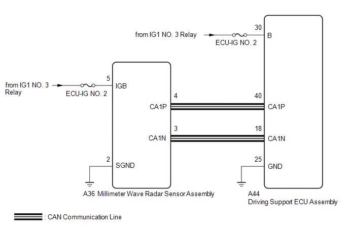
WIRING DIAGRAM
CAUTION / NOTICE / HINT
NOTICE:
Inspect the fuses for circuits related to this system before performing the following procedure.
PROCEDURE
|
1. |
CHECK HARNESS AND CONNECTOR (DRIVING SUPPORT ECUASSEMBLY - MILLIMETER WAVE RADAR SENSOR ASSEMBLY) |
(a) Disconnect the A44 driving support ECU assembly connector.
(b) Disconnect the A36 millimeter wave radar sensor assembly connector.
(c) Measure the resistance according to the value(s) in the table below.
Standard Resistance:
|
Tester Connection |
Condition |
Specified Condition |
|---|---|---|
|
A44-40 (CA1P) - A36-4 (CA1P) |
Always |
Below 1 Ω |
|
A44-18 (CA1N) - A36-3 (CA1N) |
Always |
Below 1 Ω |
|
A44-40 (CA1P) or A36-4 (CA1P) - Body ground |
Always |
10 kΩ or higher |
|
A44-18 (CA1N) or A36-3 (CA1N) - Body ground |
Always |
10 kΩ or higher |
| NG |

|
REPAIR OR REPLACE HARNESS OR CONNECTOR |
|

|
2. |
CHECK TERMINAL VOLTAGE (POWER SOURCE OF DRIVING SUPPORT ECU ASSEMBLY) |
|
(a) Disconnect the driving support ECU assembly connector. |
|
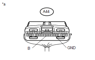
(b) Measure the voltage and resistance according to the value(s) in the table below.
Standard Voltage:
|
Tester Connection |
Switch Condition |
Specified Condition |
|---|---|---|
|
A44-30 (B) - Body ground |
Ignition switch ON |
11 to 14 V |
|
A44-30 (B) - Body ground |
Ignition switch off |
Below 1 V |
Standard Resistance:
|
Tester Connection |
Condition |
Specified Condition |
|---|---|---|
|
A44-25 (GND) - Body ground |
Always |
Below 1 Ω |
Text in Illustration
|
*a |
Rear view of wire harness connector (to Driving Support ECU Assembly) |
| NG |
|
REPAIR OR REPLACE HARNESS OR CONNECTOR (DRIVING SUPPORT ECU ASSEMBLY - BATTERY ANDBODY GROUND) |
|
|
3. |
CHECK TERMINAL VOLTAGE (POWER SOURCE OF MILLIMETER WAVERADAR SENSOR ASSEMBLY) |
|
(a) Disconnect the millimeter wave radar sensor assembly connector. |
|
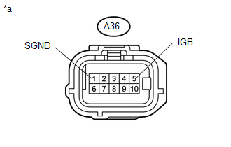
(b) Measure the voltage and resistance according to the value(s) in the table below.
Standard Voltage:
|
Tester Connection |
Switch Condition |
Specified Condition |
|---|---|---|
|
A36-5 (IGB) - Body ground |
Ignition switch ON |
11 to 14 V |
|
A36-5 (IGB) - Body ground |
Ignition switch off |
Below 1 V |
Standard Resistance:
|
Tester Connection |
Condition |
Specified Condition |
|---|---|---|
|
A36-2 (SGND) - Body ground |
Always |
Below 1 Ω |
Text in Illustration
|
*a |
Front view of wire harness connector (to Millimeter Wave radar sensor assembly) |
| NG |
|
REPAIR OR REPLACE HARNESS OR CONNECTOR (MILLIMETER WAVE RADAR SENSOR ASSEMBLY -BATTERY AND BODY GROUND) |
|
|
4. |
REPLACE MILLIMETER WAVE RADAR SENSOR ASSEMBLY |
(a) Replace the millimeter wave radar sensor assembly with a new one (See page
![2016 - 2017 MY Sienna [12/2015 - 11/2017]; CRUISE CONTROL: MILLIMETER WAVE RADAR SENSOR: REMOVAL](/t3Portal/stylegraphics/info.gif) ).
).
(b) Perform millimeter wave radar sensor assembly adjustment (See page
).
|
|
5. |
CHECK FOR DTCs (PRE-COLLISION 2) |
(a) Clear the DTCs (See page
).
(b) Make sure that the DTC detection conditions are met.
HINT:
If the detection conditions are not met, the system cannot detect the malfunction.
(c) Check for DTCs (See page
).
NOTICE:
When replacing the driving support ECU assembly, always replace it with a new one. If a driving support ECU assembly which was installed to another vehicle is used, the information stored in the driving support ECU assembly will not match the information from the vehicle. As a result, a DTC may be stored.
Result
|
Result |
Proceed to |
|---|---|
|
DTC U0235 and U1104 are not output |
A |
|
DTC U0235 or U1104 is output |
B |
| A |
|
END (MILLIMETER WAVE RADAR SENSOR ASSEMBLY WAS DEFECTIVE) |
| B |
|
REPLACE DRIVING SUPPORT ECU ASSEMBLY |
|
|
|