| Last Modified: 08-28-2024 | 6.11:8.1.0 | Doc ID: RM100000000VJSM |
| Model Year Start: 2016 | Model: Sienna | Prod Date Range: [12/2015 - 11/2017] |
| Title: PRE-COLLISION: PRE-COLLISION SYSTEM: TERMINALS OF ECU; 2016 - 2017 MY Sienna [12/2015 - 11/2017] | ||
TERMINALS OF ECU
1. CHECK SEAT BELT CONTROL ECU
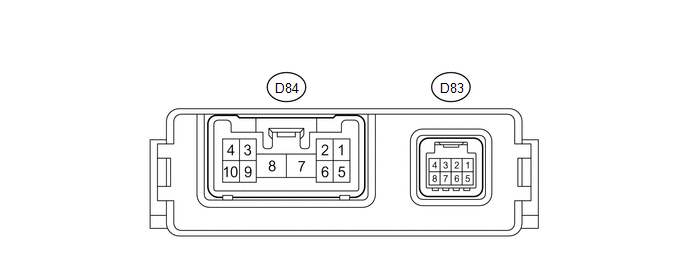
(a) Disconnect the seat belt control ECU connectors.
(b) Measure the resistance and voltage according to the value(s) in the table below.
|
Terminal No. (Symbol) |
Wiring Color |
Terminal Description |
Condition |
Specified Condition |
|---|---|---|---|---|
|
D84-7 (+B) - Body ground |
R - Body ground |
Battery voltage |
Always |
11 to 14 V |
|
D84-8 (PGND) - Body ground |
W-B - Body ground |
Body ground |
Always |
Below 1 Ω |
|
D83-8 (IG1) - Body ground |
L - Body ground |
Seat belt control ECU power supply |
Ignition switch ON |
11 to 14 V |
|
Ignition switch off |
Below 1 V |
If the result is not as specified, there may be a malfunction on the wire harness side.
(c) Reconnect the connectors.
(d) Measure the voltage according to the value(s) in the table below.
|
Terminal No. (Symbol) |
Wiring Color |
Terminal Description |
Condition |
Specified Condition |
|---|---|---|---|---|
|
D84-2 (MOR+) - D84-1 (MOR-) |
G - W |
Seat belt motor RH power supply |
Ignition switch ON |
4.0 to 8.5 V |
|
Ignition switch off |
Below 1 V |
|||
|
D84-3 (MOL+) - D84-4 (MOL-) |
Y - B |
Seat belt motor LH power supply |
Ignition switch ON |
4.0 to 8.5 V |
|
Ignition switch off |
Below 1 V |
If the result is not as specified, the ECU may be malfunctioning.
2. CHECK DRIVING SUPPORT ECU

(a) Disconnect the driving support ECU connector.
(b) Measure the voltage and resistance according to the value(s) in the table below.
|
Terminal No. (Symbol) |
Wiring Color |
Terminal Description |
Condition |
Specified Condition |
|---|---|---|---|---|
|
A44-30 (B) - Body ground |
L - Body ground |
Power supply |
Ignition switch ON |
11 to 14 V |
|
Ignition switch off |
Below 1 V |
|||
|
A44-25 (GND) - Body ground |
BR - Body ground |
Body ground |
Always |
Below 1 Ω |
|
A44-5 (PBSW) - Body ground |
P - Body ground |
Pre-collision brake cancel switch |
Pre-collision brake cancel switch on |
Below 1 Ω |
|
Pre-collision brake cancel switch off |
10 kΩ or higher |
If the result is not as specified, there may be a malfunction on the wire harness side.
(c) Reconnect the connector.
(d) Measure the voltage check for pulses according to the value(s) in the table below.
|
Terminal No. (Symbols) |
Wiring Color |
Terminal Description |
Condition |
Specified Condition |
|---|---|---|---|---|
|
A44-17 (CA2L) - A44-25 (GND) |
W - BR |
CAN communication signal |
Ignition switch ON |
Pulse generation (See waveform 1) |
|
A44-39 (CA2H) - A44-25 (GND) |
R - BR |
CAN communication signal |
Ignition switch ON |
Pulse generation (See waveform 2) |
|
A44-18 (CA1N) - A44-25 (GND) |
W - BR |
CAN communication signal |
Ignition switch ON |
Pulse generation (See waveform 3) |
|
A44-40 (CA1P) - A44-25 (GND) |
B - BR |
CAN communication signal |
Ignition switch ON |
Pulse generation (See waveform 4) |
(e) WAVEFORM 1 (Reference)
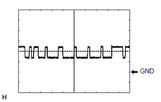
(1) CAN communication signal
|
Driving support ECU Terminal Name |
Between CA2L and GND |
|
Tester Range |
1 V/DIV., 10 μsec./DIV. |
|
Condition |
Ignition switch ON |
HINT:
The waveform varies depending on the CAN communication signal.
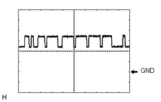
(f) WAVEFORM 2 (Reference)

(1) CAN communication signal
|
Driving support ECU Terminal Name |
Between CA2H and GND |
|
Tester Range |
1 V/DIV., 10 μsec./DIV. |
|
Condition |
Ignition switch ON |
(g) Waveform 3
(1) CAN communication signal
|
Driving support ECU Terminal Name |
Between CA1N and GND |
|
Tool Setting |
1 V/DIV., 10 μsec./DIV |
|
Condition |
Ignition switch ON |
(h) Waveform 4
(1) CAN communication signal
|
Driving support ECU Terminal Name |
Between CA1P and GND |
|
Tool Setting |
1 V/DIV., 10 μsec./DIV |
|
Condition |
Ignition switch ON |
|
|
|