| Last Modified: 08-28-2024 | 6.11:8.1.0 | Doc ID: RM100000000VJQL |
| Model Year Start: 2016 | Model: Sienna | Prod Date Range: [12/2015 - ] |
| Title: SUPPLEMENTAL RESTRAINT SYSTEMS: AIRBAG SYSTEM: SRS Warning Light Remains ON; 2016 - 2020 MY Sienna [12/2015 - ] | ||
|
SRS Warning Light Remains ON |
DESCRIPTION
The SRS warning light is located on the combination meter.
When the SRS condition is normal, the SRS warning light illuminates for approximately 6 seconds after the ignition switch is turned from off to ON, and then goes off automatically.
If there is a malfunction in the SRS, the SRS warning light illuminates or blinks to inform the driver of the problem. When terminals TC and CG of the DLC3 are connected, the SRS warning light blinks to indicate DTCs.
The center airbag sensor assembly is equipped with a voltage-increase circuit (DC-DC converter) in case the source voltage decreases. When the battery voltage decreases, the voltage-increase circuit (DC-DC converter) boosts the SRS voltage up to the normal level.
Malfunctions relating to battery voltage decreases cause the SRS warning light to illuminate. However, no DTCs are recorded in the center airbag sensor assembly. The SRS warning light goes off automatically when the source voltage returns to normal.
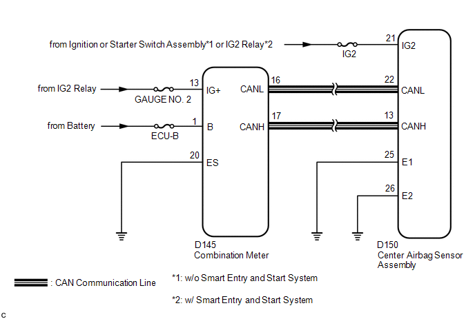
Signals to illuminate the SRS warning light are transmitted from the center airbag sensor assembly to the combination meter through the CAN communication system.
WIRING DIAGRAM
CAUTION / NOTICE / HINT
NOTICE:
Inspect the fuses for circuits related to this system before performing the following inspection procedure.
PROCEDURE
|
1. |
CHECK FOR DTC (CAN COMMUNICATION SYSTEM) |
(a) Turn the ignition switch to ON.
(b) Check the DTCs (See page
![2016 - 2020 MY Sienna [12/2015 - ]; SUPPLEMENTAL RESTRAINT SYSTEMS: AIRBAG SYSTEM: DTC CHECK / CLEAR](/t3Portal/stylegraphics/info.gif) ).
).
OK:
DTC is not output.
| NG |

|
GO TO CAN COMMUNICATION SYSTEM (See page
|
|

|
2. |
INSPECT BATTERY |
(a) Measure the voltage of the battery.
Standard Voltage:
|
Tester Connection |
Condition |
Specified Condition |
|---|---|---|
|
Battery |
Always |
11 to 14 V |
| NG |
|
CHECK AND REPLACE BATTERY OR CHARGING SYSTEM |
|
|
3. |
CHECK CONNECTION OF CONNECTORS |
(a) Turn the ignition switch off.
(b) Disconnect the cable from the negative (-) battery terminal, and wait for at least 90 seconds.
(c) Check that the connectors are properly connected to the center airbag sensor assembly and combination meter.
OK:
The connectors are properly connected.
| NG |
|
CONNECT CONNECTORS PROPERLY |
|
|
4. |
CHECK HARNESS AND CONNECTOR (SOURCE VOLTAGE OF CENTER AIRBAG SENSOR ASSEMBLY) |
|
(a) Disconnect the connectors from the center airbag sensor assembly. |
|
(b) Connect the cable to the negative battery terminal, and wait for at least 2 seconds.
(c) Turn the ignition switch to ON.
(d) Operate all components of the electrical system (defogger, wipers, headlights, heater blower, etc.).
(e) Measure the voltage according to the value(s) in the table below.
Standard Voltage:
|
Tester Connection |
Switch Condition |
Specified Condition |
|---|---|---|
|
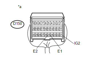
D150-21 (IG2) - D150-25 (E1) |
Ignition switch ON |
11 to 14 V |
|
D150-21 (IG2) - D150-26 (E2) |
Ignition switch ON |
11 to 14 V |
Text in Illustration
|
*a |
Rear view of wire harness connector (to Center Airbag Sensor Assembly) |
| NG |
|
REPLACE HARNESS AND CONNECTOR |
|
|
5. |
CHECK HARNESS AND CONNECTOR (SOURCE VOLTAGE OF COMBINATION METER) |
|
(a) Disconnect the cable from the negative (-) battery terminal, and wait for at least 90 seconds. |
|
(b) Disconnect the connector from the combination meter.
(c) Connect the cable to the negative battery terminal, and wait for at least 2 seconds.
(d) Turn the ignition switch to ON.
(e) Measure the voltage according to the value(s) in the table below.
Standard Voltage:
|
Tester Connection |
Switch Condition |
Specified Condition |
|---|---|---|
|
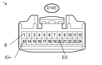
D145-1 (B) - D145-20 (ES) |
Always |
11 to 14 V |
|
D145-13 (IG+) - D145-20 (ES) |
Ignition switch ON |
11 to 14 V |
Text in Illustration
|
*a |
Front view of wire harness connector (to Combination Meter) |
| NG |
|
REPAIR OR REPLACE HARNESS OR CONNECTOR |
|
|
6. |
CHECK SRS WARNING LIGHT |
(a) Turn the ignition switch off.
(b) Disconnect the cable from the negative (-) battery terminal, and wait for at least 90 seconds.
(c) Connect the connector to the combination meter.
(d) Connect the cable to the negative battery terminal, and wait for at least 2 seconds.
(e) Turn the ignition switch to ON.
(f) Check the SRS warning light condition.
OK:
The SRS warning light goes off after the primary check period and comes on again after approximately 10 seconds.
HINT:
The primary check period lasts for approximately 6 seconds after the ignition switch is turned to ON.
| OK |
|
| NG |
|
|
|
|