| Last Modified: 08-28-2024 | 6.11:8.1.0 | Doc ID: RM100000000VJQG |
| Model Year Start: 2016 | Model: Sienna | Prod Date Range: [12/2015 - ] |
| Title: SUPPLEMENTAL RESTRAINT SYSTEMS: AIRBAG SYSTEM: DIAGNOSIS SYSTEM; 2016 - 2020 MY Sienna [12/2015 - ] | ||
DIAGNOSIS SYSTEM
1. CHECK DLC3 (See page
![2016 - 2020 MY Sienna [12/2015 - ]; INTRODUCTION: HOW TO TROUBLESHOOT ECU CONTROLLED SYSTEMS: GENERAL INFORMATION](/t3Portal/stylegraphics/info.gif) )
)
2. SYMPTOM SIMULATION
HINT:
The most difficult case in troubleshooting is when no problem symptoms occur. In such a case, a thorough problem analysis must be carried out. A simulation of the same or similar conditions and environment in which the problem occurred in the customer's vehicle should be carried out. No matter how much skill or experience a technician has, troubleshooting without confirming the problem symptoms will lead to important repairs being overlooked and mistakes or delays.
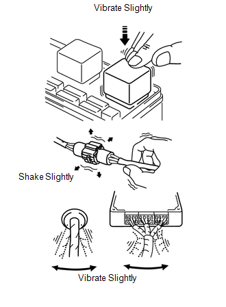
(a) Vibration method: When vibration seems to be the major cause.
HINT:
Perform the simulation method only during the primary check period (for approximately 6 seconds after the ignition switch is turned to ON).
(1) Slightly vibrate the part of the sensor considered to be the problem cause with your fingers and check whether the malfunction occurs.
NOTICE:
Shaking the relays too strongly may result in open relays.
(2) Slightly shake the connector vertically and horizontally.
(3) Slightly shake the wire harness vertically and horizontally.
HINT:
The connector joint and fulcrum of the vibration are the major areas to be checked thoroughly.
3. FUNCTION OF SRS WARNING LIGHT
(a) Primary check.
(1) Turn the ignition switch off. Wait for at least 2 seconds and then turn the ignition switch to ON. The SRS warning light comes on for approximately 6 seconds and the diagnosis of the airbag system (including the seat belt pretensioners) is performed.
HINT:
If trouble is detected during the primary check, the SRS warning light remains on even after the primary check period (of approximately 6 seconds) has elapsed.
(b) Constant check.
(1) After the primary check, the center airbag sensor constantly monitors the airbag system for trouble.
HINT:
If trouble is detected during the constant check, the center airbag sensor functions as follows:
- The SRS warning light comes on.
- The SRS warning light goes off, and then comes on. This blinking pattern indicates a source voltage drop. The SRS warning light goes off 10 seconds after the source voltage returns to normal.
(c) Review.
(1) When the airbag system is normal:
The SRS warning light comes on only during the primary check period (for approximately 6 seconds after the ignition switch is turned to ON).
(2) When the airbag system has trouble:
- The SRS warning light remains on even after the primary check period has elapsed.
- The SRS warning light goes off after the primary check, but comes on again during the constant check.
- The SRS warning light does not come on when turning the ignition switch from off to ON.
HINT:
The center airbag sensor functions to keep the SRS warning light on if the airbag has been deployed.
4. CHECK SRS WARNING LIGHT
(a) Turn the ignition switch to ON, and check that the SRS warning light comes on for approximately 6 seconds (primary check).
(b) Check that the SRS warning light goes off approximately 6 seconds after the ignition switch is turned to ON (constant check).
HINT:
When any of the following symptoms occur, refer to "Problem Symptoms Table" (See page
).
- The SRS warning light comes on occasionally, after the primary check period has elapsed.
- The SRS warning light comes on, but a DTC is not output.
- The ignition switch is turned from off to ON, but the SRS warning light does not come on.
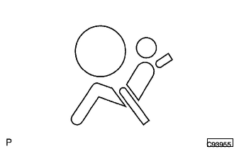
5. FUNCTION OF PASSENGER AIRBAG ON/OFF INDICATOR
(a) Initial check
(1) Turn the ignition switch to ON.
(2) The passenger airbag ON/OFF indicator (ON and OFF) comes on for approximately 4 seconds, and then goes off for approximately 2 seconds.
(3) Approximately 6 seconds after the ignition switch is turned to ON, the passenger airbag ON/OFF indicator will be ON/OFF depending on the conditions listed below.
|
Front Seat Passenger |
Passenger Airbag ON/OFF Indicator |
SRS Warning Light |
|
|---|---|---|---|
|
ON Indicator |
OFF Indicator |
||
|
Adult seated |
ON |
OFF |
OFF |
|
Child seated/Child restraint system set |
OFF |
ON |
OFF |
|
Vacant |
OFF |
OFF |
OFF |
|
Passenger occupant classification system failure |
OFF |
ON |
ON |
HINT:
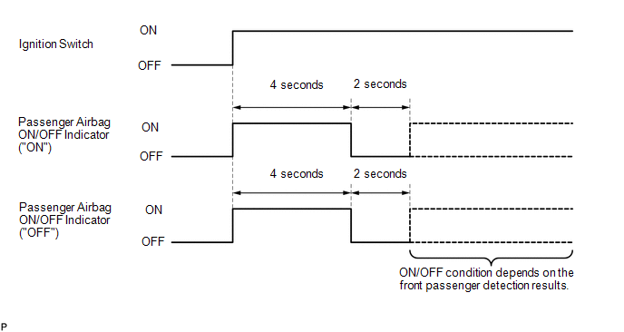
- The passenger airbag ON/OFF indicator operates based on the timing chart below in order to check the indicator light circuit.
- When the occupant classification system has trouble, both the SRS warning light and the passenger airbag ON/OFF indicator (OFF) come on. In this case, check the DTCs in Airbag System first. Then troubleshoot the occupant classification system if DTC B1650/32 is detected, and troubleshoot the passenger airbag ON/OFF indicator if DTC B1660/43 is detected.
6. CHECK PASSENGER AIRBAG ON/OFF INDICATOR
(a) Turn the ignition switch to ON.
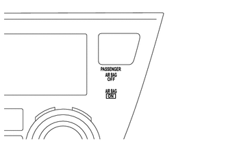
(b) Check that the passenger airbag ON/OFF indicator (ON and OFF) comes on for approximately 4 seconds, and then goes off for approximately 2 seconds.
HINT:
Refer to the table in the previous step regarding the passenger airbag ON/OFF indicator when approximately 6 seconds have elapsed after the ignition switch is turned to ON.
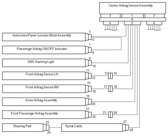
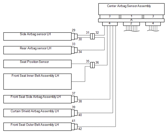
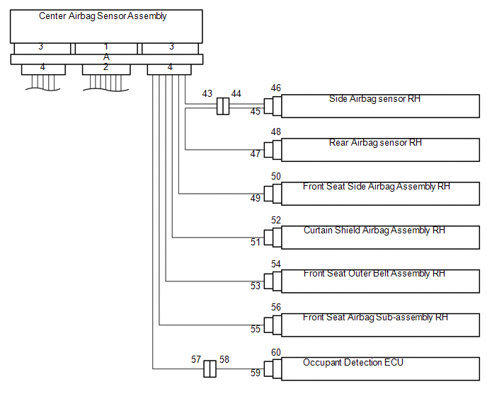
7. SRS CONNECTORS
(a) SRS connectors are located as shown in the following illustration.
|
Connector Type |
Application |
|---|---|
|
Terminal Twin-lock Mechanism |
Connectors 2, 4, 8, 13, 14, 17, 18, 28, 30, 31, 32, 34, 38, 43, 44, 45, 47, 49 |
|
Half Connection Prevention Mechanism |
Connectors 24, 25, 41, 52 |
|
Activation Prevention Mechanism |
Connectors 2, 4, 19, 21, 23, 27, 37, 39, 50, 54 |
|
Connector Lock Mechanism (1) |
Connectors 20, 22, 26, 40, 42, 53 |
|
Connector Position Assurance Mechanism |
Connectors 6, 16 |
|
Connector Lock Mechanism (2) |
Connector A |
|
Improper Connection Prevention Lock Mechanism |
Connector A |
(b) All connectors in the SRS are colored yellow to distinguish them from other connectors. These connectors have special functions, and are specially designed for the SRS. All SRS connectors use durable gold-plated terminals, and are placed in the locations shown below to ensure high reliability.
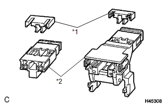
Text in Illustration
|
*1 |
Spacer |
|
*2 |
Housing |
(1) Terminal twin-lock mechanism:
All connectors with a terminal twin-lock mechanism have a two-piece component consisting of a housing and a spacer. This design enables the terminal to be locked securely by two locking devices (the retainer and the lance) to prevent terminals from coming out.
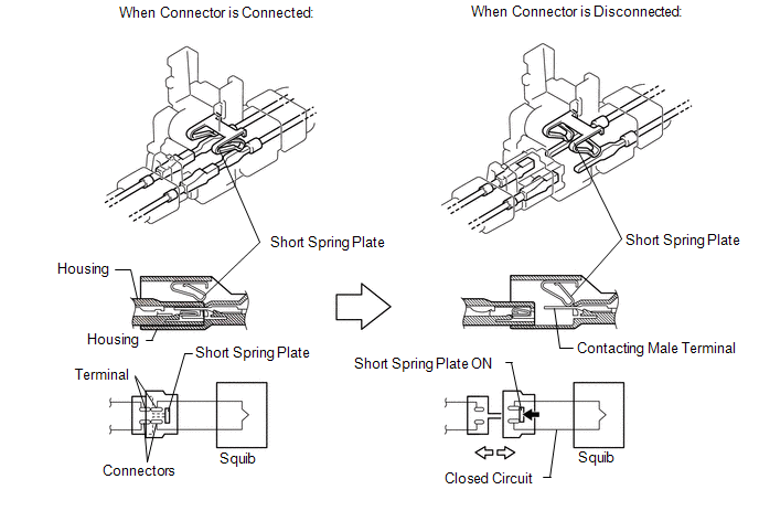
(2) Activation prevention mechanism:
All connectors with an activation prevention mechanism contain a short spring plate. When these connectors are disconnected, the short spring plate creates a short circuit by automatically connecting the positive (+) and negative (-) terminals of the squib.
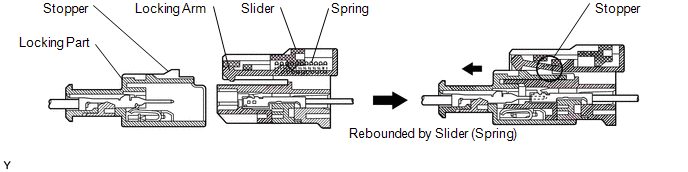
(3) Half connection prevention mechanism:
If the connector is not completely connected, the connector is disconnected by the spring force so that no continuity exists.
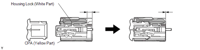
(4) Connector position assurance mechanism:
Only when the housing lock (white part) is completely engaged, the CPA (yellow part) slides, which completes the connector engagement.
(5) Connector lock mechanism (1):
Locking the connector lock button connects the connector securely.

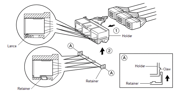
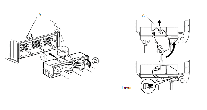
(6) Connector lock mechanism (2):
Both the primary lock with holder lances and the secondary lock with retainer prevent the connectors from becoming disconnected.
(7) Improper connection prevention lock mechanism:
When connecting the holder, the lever is pushed into the lock position by rotating around the A axis to lock the holder securely.
8. ACTIVATION PREVENTION MECHANISM
(a) FUNCTION OF ACTIVATION PREVENTION MECHANISM
(1) An activation prevention mechanism is built into the connector (on the center airbag sensor assembly side) of the airbag system squib circuit to prevent accidental airbag activation.
(2) This mechanism closes the circuit when the connector is disconnected by bringing the short spring into contact with the terminals and shutting off external electricity to prevent accidental airbag activation.
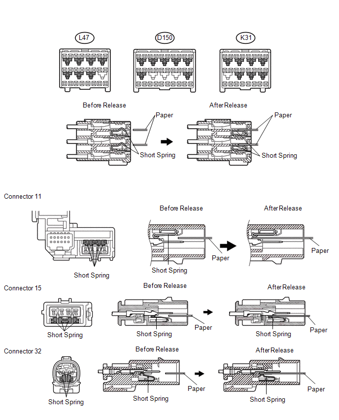
(b) RELEASING OF ACTIVATION PREVENTION MECHANISM
(1) To release the activation prevention mechanism, insert a piece of paper with the same thickness as the male terminal (approximately 0.5 mm (0.020 in.)) between the terminals and the short spring to break the connection.
(2) Refer to the following illustrations concerning connectors utilizing the activation prevention mechanism and its release method.
CAUTION:
Never release the activation prevention mechanism on the squib connector even when inspecting with the squib disconnected.
NOTICE:
- Do not release the activation prevention mechanism unless specially directed by the troubleshooting procedure.
- To prevent the terminal and the short spring from being damaged, always use a piece of paper with the same thickness as the male terminal.
|
|
|