| Last Modified: 08-28-2024 | 6.11:8.1.0 | Doc ID: RM100000000VJO1 |
| Model Year Start: 2016 | Model: Sienna | Prod Date Range: [12/2015 - 08/2016] |
| Title: METER / GAUGE / DISPLAY: METER / GAUGE SYSTEM: Speed Signal Circuit; 2016 MY Sienna [12/2015 - 08/2016] | ||
|
Speed Signal Circuit |
DESCRIPTION
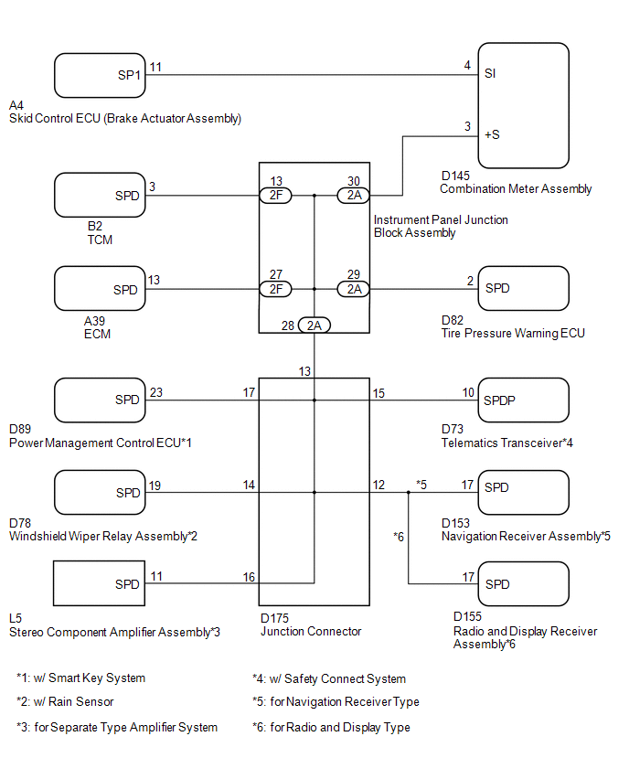
The combination meter assembly receives the vehicle speed signal from this circuit. The wheel speed sensors produce an output that varies according to the vehicle speed. The wheel speed sensor output is received by the skid control ECU, which uses this information to create the vehicle speed sensor signal*1. The vehicle speed sensor signal consists of pulses sent to the combination meter assembly from the skid control ECU. To create this signal, 12 V is output from IG2, which is behind a resistor in the combination meter assembly. This voltage is sent to the skid control ECU. The pulse signal is created by switching the transistor in the skid control ECU on and off, making the voltage on the wire drop to 0 V. A similar system is used for the output of this signal from the combination meter assembly via terminal +S. A voltage of 12 V or 5 V is applied to terminal +S from each ECU or relay that is connected to this terminal. The transistor in the combination meter assembly is controlled by the signal from the skid control ECU. When this transistor is turned on, this transistor makes the voltage supplied by the various ECUs (via their respective internal resistors) drop to 0 V. Each ECU connected to terminal +S of the combination meter assembly controls its respective system based on the pulse signal.
- *1: This vehicle speed sensor signal is created by the skid control ECU. There is no actual component that is referred to as the vehicle speed sensor. In addition, for some other systems, vehicle speed information may be exchanged using CAN communication.
HINT:
This circuit is used for the systems connected to terminal +S. This signal is not used for combination meter assembly operation. Combination meter assembly components such as the speedometer operate using data received via CAN communication.
WIRING DIAGRAM
PROCEDURE
|
1. |
INSPECT COMBINATION METER ASSEMBLY (INPUT VOLTAGE) |
|
(a) Disconnect the combination meter assembly connector. |
|
(b) Measure the voltage according to the value(s) in the table below.
Standard Voltage:
|
Tester Connection |
Switch Condition |
Specified Condition |
|---|---|---|
|
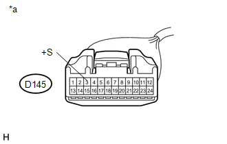
D145-3 (+S) - Body ground |
Ignition switch ON |
4.5 to 14 V |
Text in Illustration
|
*a |
Front view of wire harness connector (to Combination Meter Assembly) |
HINT:
If any of the ECUs specified in the wiring diagram supplies power to the combination meter assembly, the combination meter assembly will output a waveform.
| NG |

|
|

|
2. |
INSPECT COMBINATION METER ASSEMBLY (OUTPUT VOLTAGE) |
|
(a) Disconnect the A4 brake actuator assembly connector. |
|
(b) Measure the voltage according to the value(s) in the table below.
Standard Voltage:
|
Tester Connection |
Switch Condition |
Specified Condition |
|---|---|---|
|
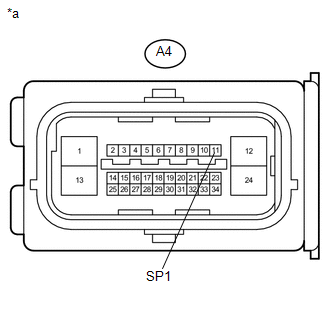
A4-11 (SP1) - Body ground |
Ignition switch ON |
11 to 14 V |
Text in Illustration
|
*a |
Front view of wire harness connector (to Brake Actuator Assembly) |
| NG |
|
|
|
3. |
INSPECT BRAKE ACTUATOR ASSEMBLY (INPUT WAVEFORM) |
|
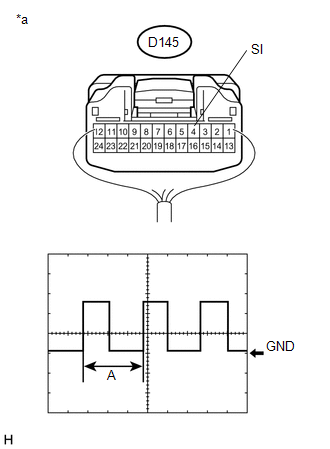
(a) Check the input waveform. (1) Remove the combination meter assembly with the connector(s) still connected. (2) Connect an oscilloscope to terminal D145-4 (SI) and body ground. (3) Turn the ignition switch to ON. (4) Turn the wheel slowly. (5) Check the signal waveform according to the condition(s) in the table below.
OK: The waveform is similar to that shown in the illustration. HINT: When the system is functioning normally, one wheel revolution generates 4 pulses. As the vehicle speed increases, the width indicated by (A) in the illustration narrows. Text in Illustration
|
|
| OK |
|
| NG |
|
|
4. |
CHECK HARNESS AND CONNECTOR (BRAKE ACTUATOR ASSEMBLY - COMBINATION METER ASSEMBLY) |
(a) Disconnect the A4 brake actuator assembly connector.
(b) Disconnect the D145 combination meter assembly connector.
(c) Measure the resistance according to the value(s) in the table below.
Standard Resistance:
|
Tester Connection |
Condition |
Specified Condition |
|---|---|---|
|
A4-11 (SP1) - D145-4 (SI) |
Always |
Below 1 Ω |
|
A4-11 (SP1) or D145-4 (SI) - Body ground |
Always |
10 kΩ or higher |
| OK |
|
| NG |
|
REPAIR OR REPLACE HARNESS OR CONNECTOR |
|
5. |
CHECK HARNESS AND CONNECTOR (COMBINATION METER ASSEMBLY - INSTRUMENT PANEL JUNCTION BLOCK ASSEMBLY) |
(a) Disconnect the D145 combination meter assembly connector.
(b) Disconnect the 2A instrument panel junction block assembly connector.
(c) Measure the resistance according to the value(s) in the table below.
Standard Resistance:
|
Tester Connection |
Condition |
Specified Condition |
|---|---|---|
|
D145-3 (+S) - 2A-30 |
Always |
Below 1 Ω |
|
D145-3 (+S) or 2A-30 - Body ground |
Always |
10 kΩ or higher |
| NG |
|
REPAIR OR REPLACE HARNESS OR CONNECTOR |
|
|
6. |
CHECK HARNESS AND CONNECTOR (INSTRUMENT PANEL JUNCTION BLOCK ASSEMBLY) |
(a) Inspect for a short in the circuit that is connected to the instrument panel junction block assembly connector shown in the wiring diagram.
HINT:
If the voltage is not as specified, it is possible that an ECU or circuit has a malfunction. The malfunctioning ECU or circuit will be diagnosed in the following steps.
|
(1) Disconnect the 2A and 2F instrument panel junction block assembly connectors. |
|
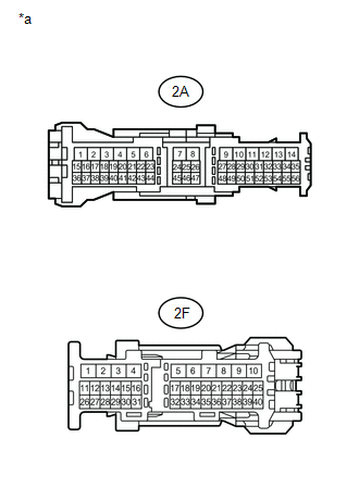
(2) Measure the voltage according to the value(s) in the table below.
Standard Voltage:
|
Tester Connection |
Switch Condition |
Specified Condition |
|---|---|---|
|
2F-13 - Body ground |
Ignition switch ON |
4.5 to 14 V |
|
2F-27 - Body ground |
Ignition switch ON |
4.5 to 14 V |
|
2A-29 - Body ground |
Ignition switch ON |
4.5 to 14 V |
|
2A-28 - Body ground |
Ignition switch ON |
4.5 to 14 V |
Text in Illustration
|
*a |
Front view of wire harness connector (to Instrument Panel Junction Block Assembly) |
Result
|
Result |
Proceed to |
|---|---|
|
Voltage is not as specified in one circuit |
A |
|
Voltage is as specified in all circuits |
B |
| B |
|
REPLACE INSTRUMENT PANEL JUNCTION BLOCK ASSEMBLY |
|
|
7. |
SYSTEM CHECK |
(a) Select the circuit for which voltage was not as specified in the previous step 6.
Result
|
Tester Connection |
System that Uses the Circuit |
Proceed to |
|---|---|---|
|
2F-13 - Body ground |
Automatic transaxle system |
A |
|
2F-27 - Body ground |
SFI system |
B |
|
2A-29 - Body ground |
Tire pressure warning system |
C |
|
2A-28 - Body ground |
Smart key system*1, wiper and washer system*2, separate type amplifier system*3, safety connect system*4, navigation system*5, audio and visual system*6 |
D |
- *1: w/ Smart Key System
- *2: w/ Rain Sensor
- *3: for Separate Type Amplifier System
- *4: w/ Safety Connect System
- *5: for Navigation Receiver Type
- *6: for Radio and Display Type
| B |
|
| C |
|
| D |
|
|
|
8. |
CHECK HARNESS AND CONNECTOR (INSTRUMENT PANEL JUNCTION BLOCK ASSEMBLY - TCM) |
(a) Disconnect the 2F instrument panel junction block assembly connector.
(b) Disconnect the B2 TCM connector.
(c) Measure the resistance according to the value(s) in the table below.
Standard Resistance:
|
Tester Connection |
Condition |
Specified Condition |
|---|---|---|
|
2F-13 - B2-3 (SPD) |
Always |
Below 1 Ω |
|
2F-13 or B2-3 (SPD) - Body ground |
Always |
10 kΩ or higher |
| OK |
|
| NG |
|
REPAIR OR REPLACE HARNESS OR CONNECTOR |
|
9. |
CHECK HARNESS AND CONNECTOR (INSTRUMENT PANEL JUNCTION BLOCK ASSEMBLY - ECM) |
(a) Disconnect the 2F instrument panel junction block assembly connector.
(b) Disconnect the A39 ECM connector.
(c) Measure the resistance according to the value(s) in the table below.
Standard Resistance:
|
Tester Connection |
Condition |
Specified Condition |
|---|---|---|
|
2F-27 - A39-13 (SPD) |
Always |
Below 1 Ω |
|
2F-27 or A39-13 (SPD) - Body ground |
Always |
10 kΩ or higher |
| OK |
|
| NG |
|
REPAIR OR REPLACE HARNESS OR CONNECTOR |
|
10. |
CHECK HARNESS AND CONNECTOR (INSTRUMENT PANEL JUNCTION BLOCK ASSEMBLY - TIRE PRESSURE WARNING ECU) |
(a) Disconnect the 2A instrument panel junction block assembly connector.
(b) Disconnect the D82 tire pressure warning ECU connector.
(c) Measure the resistance according to the value(s) in the table below.
Standard Resistance:
|
Tester Connection |
Condition |
Specified Condition |
|---|---|---|
|
2A-29 - D82-2 (SPD) |
Always |
Below 1 Ω |
|
2A-29 or D82-2 (SPD) - Body ground |
Always |
10 kΩ or higher |
| OK |
|
| NG |
|
REPAIR OR REPLACE HARNESS OR CONNECTOR |
|
11. |
CHECK HARNESS AND CONNECTOR (INSTRUMENT PANEL JUNCTION BLOCK ASSEMBLY - JUNCTION CONNECTOR) |
(a) Disconnect the 2A instrument panel junction block assembly connector.
(b) Disconnect the D175 junction connector.
(c) Measure the resistance according to the value(s) in the table below.
Standard Resistance:
|
Tester Connection |
Condition |
Specified Condition |
|---|---|---|
|
2A-28 - D175-13 |
Always |
Below 1 Ω |
|
2A-28 or D175-13 - Body ground |
Always |
10 kΩ or higher |
| NG |
|
REPAIR OR REPLACE HARNESS OR CONNECTOR |
|
|
12. |
CHECK HARNESS AND CONNECTOR (JUNCTION CONNECTOR) |
(a) Inspect for a short in the circuit that is connected to the junction connector shown in the wiring diagram.
|
(1) Disconnect the D175 junction connector. |
|
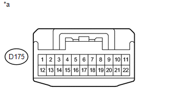
(2) Measure the voltage according to the value(s) in the table below
Standard Voltage:
|
Tester Connection |
Switch Condition |
Specified Condition |
|---|---|---|
|
D175-17 - Body ground*1 |
Ignition switch ON |
4.5 to 14 V |
|
D175-14 - Body ground*2 |
Ignition switch ON |
4.5 to 14 V |
|
D175-16 - Body ground*3 |
Ignition switch ON |
4.5 to 14 V |
|
D175-15 - Body ground*4 |
Ignition switch ON |
4.5 to 14 V |
|
D175-12 - Body ground |
Ignition switch ON |
4.5 to 14 V |
- *1: w/ Smart Key System
- *2: w/ Rain Sensor
- *3: for Separate Type Amplifier System
- *4: w/ Safety Connect System
Text in Illustration
|
*a |
Front view of wire harness connector (to Junction Connector) |
Result
|
Result |
Proceed to |
|---|---|
|
Voltage is not as specified in one circuit |
A |
|
Voltage is as specified in all circuits |
B |
| B |
|
REPLACE JUNCTION CONNECTOR |
|
|
13. |
SYSTEM CHECK |
(a) Select the circuit for which voltage was not as specified in the previous step 12.
Result
|
Tester Connection |
System that Uses the Circuit |
Proceed to |
|---|---|---|
|
D175-17 - Body ground*1 |
Smart key system |
A |
|
D175-14 - Body ground*2 |
Wiper and washer system |
B |
|
D175-16 - Body ground*3 |
Separate Type Amplifier System |
C |
|
D175-15 - Body ground*4 |
Safety connect system |
D |
|
D175-12 - Body ground |
Navigation system*5, audio and visual system*6 |
E |
- *1: w/ Smart Key System
- *2: w/ Rain Sensor
- *3: for Separate Type Amplifier System
- *4: w/ Safety Connect System
- *5: for Navigation Receiver Type
- *6: for Radio and Display Type
| B |
|
| C |
|
| D |
|
| E |
|
|
|
14. |
CHECK HARNESS AND CONNECTOR (JUNCTION CONNECTOR - POWER MANAGEMENT CONTROL ECU) |
(a) Disconnect the D175 junction connector.
(b) Disconnect the D89 power management control ECU connector.
(c) Measure the resistance according to the value(s) in the table below.
Standard Resistance:
|
Tester Connection |
Condition |
Specified Condition |
|---|---|---|
|
D175-17 - D89-23 (SPD) |
Always |
Below 1 Ω |
|
D175-17 or D89-23 (SPD) - Body ground |
Always |
10 kΩ or higher |
| OK |
|
| NG |
|
REPAIR OR REPLACE HARNESS OR CONNECTOR |
|
15. |
CHECK HARNESS AND CONNECTOR (JUNCTION CONNECTOR - WINDSHIELD WIPER RELAY ASSEMBLY) |
(a) Disconnect the D175 junction connector.
(b) Disconnect the D78 windshield wiper relay assembly connector.
(c) Measure the resistance according to the value(s) in the table below.
Standard Resistance:
|
Tester Connection |
Condition |
Specified Condition |
|---|---|---|
|
D175-14 - D78-19 (SPD) |
Always |
Below 1 Ω |
|
D175-14 or D78-19 (SPD) - Body ground |
Always |
10 kΩ or higher |
| OK |
|
| NG |
|
REPAIR OR REPLACE HARNESS OR CONNECTOR |
|
16. |
CHECK HARNESS AND CONNECTOR (JUNCTION CONNECTOR - STEREO COMPONENT AMPLIFIER ASSEMBLY) |
(a) Disconnect the D175 junction connector.
(b) Disconnect the L5 stereo component amplifier assembly connector.
(c) Measure the resistance according to the value(s) in the table below.
Standard Resistance:
|
Tester Connection |
Condition |
Specified Condition |
|---|---|---|
|
D175-16 - L5-11 (SPD) |
Always |
Below 1 Ω |
|
D175-16 or L5-11 (SPD) - Body ground |
Always |
10 kΩ or higher |
| OK |
|
| NG |
|
REPAIR OR REPLACE HARNESS OR CONNECTOR |
|
17. |
CHECK HARNESS AND CONNECTOR (JUNCTION CONNECTOR - TELEMATICS TRANSCEIVER) |
(a) Disconnect the D175 junction connector.
(b) Disconnect the D73 telematics transceiver connector.
(c) Measure the resistance according to the value(s) in the table below.
Standard Resistance:
|
Tester Connection |
Condition |
Specified Condition |
|---|---|---|
|
D175-15 - D73-10 (SPDP) |
Always |
Below 1 Ω |
|
D175-15 or D73-10 (SPDP) - Body ground |
Always |
10 kΩ or higher |
| OK |
|
| NG |
|
REPAIR OR REPLACE HARNESS OR CONNECTOR |
|
18. |
CHECK HARNESS AND CONNECTOR (JUNCTION CONNECTOR - NAVIGATION RECEIVER ASSEMBLY OR RADIO AND DISPLAY RECEIVER ASSEMBLY) |
(a) for Navigation Receiver Type
(1) Disconnect the D175 junction connector.
(2) Disconnect the D153 navigation receiver assembly connector.
(3) Measure the resistance according to the value(s) in the table below.
Standard Resistance:
|
Tester Connection |
Condition |
Specified Condition |
|---|---|---|
|
D175-12 - D153-17 (SPD) |
Always |
Below 1 Ω |
|
D175-12 or D153-17 (SPD) - Body ground |
Always |
10 kΩ or higher |
(b) for Radio and Display Type
(1) Disconnect the D175 junction connector.
(2) Disconnect the D155 radio and display receiver assembly connector.
(3) Measure the resistance according to the value(s) in the table below.
Standard Resistance:
|
Tester Connection |
Condition |
Specified Condition |
|---|---|---|
|
D175-12 - D155-17 (SPD) |
Always |
Below 1 Ω |
|
D175-12 or D155-17 (SPD) - Body ground |
Always |
10 kΩ or higher |
Result
|
Result |
Proceed to |
|---|---|
|
NG |
A |
|
OK (for Navigation Receiver Type) |
B |
|
OK (for Radio and Display Type) |
C |
| A |
|
REPAIR OR REPLACE HARNESS OR CONNECTOR |
| B |
|
| C |
|
|
|
|