| Last Modified: 08-28-2024 | 6.11:8.1.0 | Doc ID: RM100000000VJO0 |
| Model Year Start: 2016 | Model: Sienna | Prod Date Range: [12/2015 - ] |
| Title: METER / GAUGE / DISPLAY: METER / GAUGE SYSTEM: Entire Combination Meter does not Operate; 2016 - 2020 MY Sienna [12/2015 - ] | ||
|
Entire Combination Meter does not Operate |
DESCRIPTION
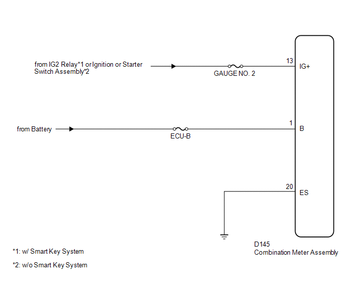
This circuit is the power source circuit for the meter. This circuit provides two types of power sources, one is a constant power source mainly used as a backup power source, and the other is an IG power source mainly used for signal transmission. The constant power source is mainly used as a backup power source for the meter CPU, however, it is also used for CAN communication. If a voltage of 12 V is not applied to terminal IG+ when turning the ignition switch ON, the indicators will not operate.
WIRING DIAGRAM
CAUTION / NOTICE / HINT
CAUTION:
Inspect the fuses for circuits related to this system before performing the following inspection procedure.
PROCEDURE
|
1. |
CHECK HARNESS AND CONNECTOR (COMBINATION METER ASSEMBLY - BATTERY AND BODY GROUND) |
|
(a) Disconnect the combination meter assembly connector. |
|
(b) Measure the voltage according to the value(s) in the table below.
Standard Voltage:
|
Tester Connection |
Switch Condition |
Specified Condition |
|---|---|---|
|
D145-13 (IG+) - Body ground |
Ignition switch ON |
11 to 14 V |
|
D145-1 (B) - Body ground |
Always |
11 to 14 V |
(c) Measure the resistance according to the value(s) in the table below.
Standard Resistance:
|
Tester Connection |
Condition |
Specified Condition |
|---|---|---|
|
D145-20 (ES) - Body ground |
Always |
Below 1 Ω |
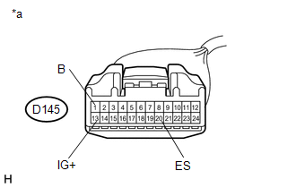
Text in Illustration
|
*a |
Front view of wire harness connector (to Combination Meter Assembly) |
| OK |

|
| NG |
|
REPAIR OR REPLACE HARNESS OR CONNECTOR |
|
|
|