| Last Modified: 08-28-2024 | 6.11:8.1.0 | Doc ID: RM100000000VJNB |
| Model Year Start: 2016 | Model: Sienna | Prod Date Range: [12/2015 - 08/2016] |
| Title: LIGHTING (INT): LIGHTING SYSTEM: Interior Light Circuit; 2016 MY Sienna [12/2015 - 08/2016] | ||
|
Interior Light Circuit |
DESCRIPTION
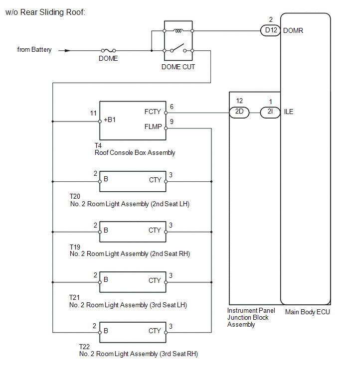
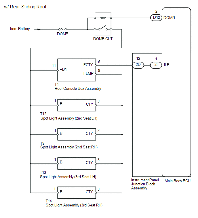
The illuminated entry system controls the No. 2 room light assembly*1, spot light assembly*2 and roof console box assembly.
- *1: w/o Rear Sliding Roof
- *2: w/ Rear Sliding Roof
WIRING DIAGRAM
PROCEDURE
|
1. |
PERFORM ACTIVE TEST USING TECHSTREAM |
(a) Connect the Techstream to the DLC3.
(b) Turn the ignition switch to ON.
(c) Turn the Techstream on.
(d) Enter the following menus: Body Electrical / Main Body / Active Test.
(e) According to the display on the Techstream, perform the Active Test.
Main Body
|
Tester Display |
Test Part |
Control Range |
Diagnostic Note |
|---|---|---|---|
|
Illuminated Entry System |
No. 2 room light assembly*1, spot light assembly*2 and roof console box assembly |
ON/OFF |
Interior light switch is in the DOOR position and all doors are closed. |
- *1: w/o Rear Sliding Roof
- *2: w/ Rear Sliding Roof
OK:
Each light fades in.
| OK |

|
PROCEED TO NEXT SUSPECTED AREA SHOWN IN PROBLEM SYMPTOMS TABLE |
|

|
2. |
CHECK HARNESS AND CONNECTOR (BATTERY - MAIN BODY ECU) |
|
(a) Disconnect the D12 main body ECU connector. |
|
(b) Measure the voltage according to the value(s) in the table below.
Standard Voltage:
|
Tester Connection |
Condition |
Specified Condition |
|---|---|---|
|
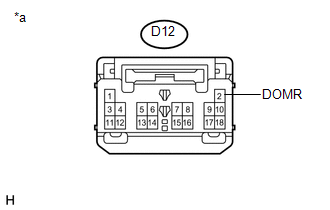
D12-2 (DOMR) - Body ground |
Always |
11 to 14 V |
Text in Illustration
|
*a |
Front view of wire harness connector (to Main Body ECU) |
(c) Reconnect the main body ECU connector.
| NG |
|
REPAIR OR REPLACE HARNESS OR CONNECTOR |
|
|
3. |
CHECK HARNESS AND CONNECTOR (BATTERY - INSTRUMENT PANEL JUNCTION BLOCK) |
|
(a) Disconnect the 2D instrument panel junction block assembly connector. |
|
(b) Measure the voltage according to the value(s) in the table below.
Standard Voltage:
|
Tester Connection |
Condition |
Specified Condition |
|---|---|---|
|
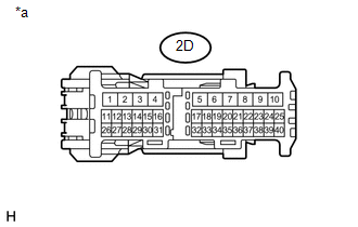
2D-12 - Body ground |
Always |
11 to 14 V |
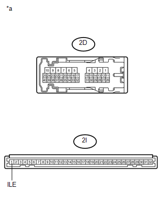
Text in Illustration
|
*a |
Front view of wire harness connector (to Instrument Panel Junction Block Assembly) |
(c) Reconnect the instrument panel junction block assembly connector.
| NG |
|
REPAIR OR REPLACE HARNESS OR CONNECTOR |
|
|
4. |
INSPECT INSTRUMENT PANEL JUNCTION BLOCK ASSEMBLY |
|
(a) Remove the instrument panel junction block assembly. |
|
(b) Measure the resistance according to the value(s) in the table below.
Standard Resistance:
|
Tester Connection |
Condition |
Specified Condition |
|---|---|---|
|
2D-12 - 2I-1 (ILE) |
Always |
Below 1 Ω |
|
2I-1 (ILE) - Body ground |
Always |
10 kΩ or higher |
Text in Illustration
|
*a |
Component without harness connected (Instrument Panel Junction Block Assembly) |
(c) Reinstall the instrument panel junction block assembly.
| OK |
|
| NG |
|
REPLACE INSTRUMENT PANEL JUNCTION BLOCK ASSEMBLY |
|
|
|