| Last Modified: 08-28-2024 | 6.11:8.1.0 | Doc ID: RM100000000VJNA |
| Model Year Start: 2016 | Model: Sienna | Prod Date Range: [12/2015 - ] |
| Title: LIGHTING (INT): LIGHTING SYSTEM: Door Courtesy Switch Circuit; 2016 - 2020 MY Sienna [12/2015 - ] | ||
|
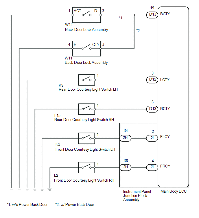
Door Courtesy Switch Circuit |
DESCRIPTION
The main body ECU detects the condition of the door courtesy light switch.
WIRING DIAGRAM
PROCEDURE
|
1. |
READ VALUE USING TECHSTREAM (COURTESY SWITCH) |
(a) Connect the Techstream to the DLC3.
(b) Turn the ignition switch to ON.
(c) Turn the Techstream on.
(d) Enter the following menus: Body Electrical / Main Body / Data List.
(e) According to the display on the Techstream, read the Data List.
Main Body
|
Tester Display |
Measurement Item/Range |
Normal Condition |
Diagnostic Note |
|---|---|---|---|
|
FL Door Courtesy |
Front door courtesy light switch LH signal/ON or OFF |
ON: Front door LH closed OFF: Front door LH open |
- |
|
FR Door Courtesy |
Front door courtesy light switch RH signal/ON or OFF |
ON: Front door RH closed OFF: Front door RH open |
- |
|
RR Door Courtesy SW |
Rear door courtesy light switch RH signal/ON or OFF |
ON: Rear door RH open OFF: Rear door RH closed |
- |
|
RL Door Courtesy SW |
Rear door courtesy light switch LH signal/ON or OFF |
ON: Rear door LH open OFF: Rear door LH closed |
- |
|
Back Door Courtesy SW |
Back door Courtesy switch signal/ON or OFF |
ON: Back door open OFF: Back door closed |
- |
OK:
Normal conditions listed above are displayed.
Result
|
Result |
Proceed to |
|---|---|
|
OK |
A |
|
Front door courtesy light switch LH or RH does not operate |
B |
|
Rear door courtesy light switch LH or RH does not operate |
C |
|
Back door courtesy switch does not operate |
D |
| A |

|
PROCEED TO NEXT SUSPECTED AREA SHOWN IN PROBLEM SYMPTOMS TABLE (See page
|
| C |
|
| D |
|
|

|
2. |
INSPECT FRONT DOOR COURTESY LIGHT SWITCH (LH OR RH) |
|
(a) Remove the front door courtesy light switch (See page
|
|
(b) Measure the resistance according to the value(s) in the table below.
Standard Resistance:
|
Tester Connection |
Switch Condition |
Specified Condition |
|---|---|---|
|
1 - Switch body |
Pushed |
10 kΩ or higher |
|
Not pushed |
Below 1 Ω |
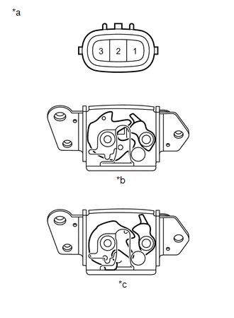
Text in Illustration
|
*a |
Component without harness connected (Front Door Courtesy Light Switch) |
|
*b |
Switch Body |
(c) Reinstall the front door courtesy light switch.
| NG |
|
|
|
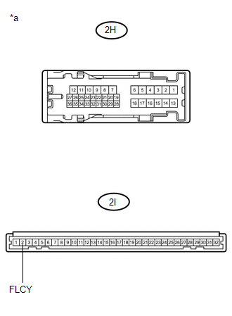
3. |
CHECK HARNESS AND CONNECTOR (INSTRUMENT PANEL JUNCTION BLOCK - COURTESY LIGHT SWITCH) |
(a) for Front LH
(1) Disconnect the 2H instrument panel junction block assembly connector.
(2) Disconnect the K2 front door courtesy light switch connector.
(3) Measure the resistance according to the value(s) in the table below.
Standard Resistance:
|
Tester Connection |
Condition |
Specified Condition |
|---|---|---|
|
2H-34 - K2-1 |
Always |
Below 1 Ω |
|
2H-34 - Body ground |
Always |
10 kΩ or higher |
(4) Reconnect the front door courtesy light switch connector.
(5) Reconnect the instrument panel junction block assembly connector.
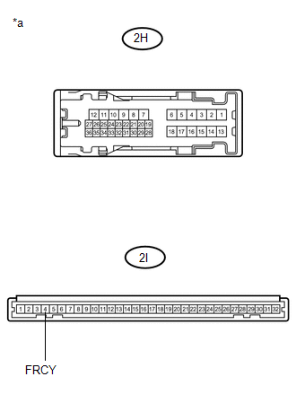
(b) for Front RH
(1) Disconnect the 2H instrument panel junction block assembly connector.
(2) Disconnect the L2 front door courtesy light switch connector.
(3) Measure the resistance according to the value(s) in the table below.
Standard Resistance:
|
Tester Connection |
Condition |
Specified Condition |
|---|---|---|
|
2H-36 - L2-1 |
Always |
Below 1 Ω |
|
2H-36 - Body ground |
Always |
10 kΩ or higher |
(4) Reconnect the front door courtesy light switch connector.
(5) Reconnect the instrument panel junction block assembly connector.
| NG |
|
REPAIR OR REPLACE HARNESS OR CONNECTOR |
|
|
4. |
INSPECT INSTRUMENT PANEL JUNCTION BLOCK ASSEMBLY |
|
(a) for Front LH (1) Remove the instrument panel junction block assembly. (2) Measure the resistance according to the value(s) in the table below. Standard Resistance:
Text in Illustration
(3) Reinstall the instrument panel junction block assembly. |
|
|
(b) for Front RH (1) Remove the instrument panel junction block assembly. (2) Measure the resistance according to the value(s) in the table below. Standard Resistance:
Text in Illustration
(3) Reinstall the instrument panel junction block assembly. |
|
| OK |
|
| NG |
|
REPLACE INSTRUMENT PANEL JUNCTION BLOCK ASSEMBLY |
|
5. |
INSPECT REAR DOOR COURTESY LIGHT SWITCH (LH OR RH) |
|
(a) Remove the rear door courtesy light switch (See page
|
|
(b) Measure the resistance according to the value(s) in the table below.
Standard Resistance:
|
Tester Connection |
Switch Condition |
Specified Condition |
|---|---|---|
|
1 - Switch body |
Pushed |
10 kΩ or higher |
|
Not pushed |
Below 1 Ω |
Text in Illustration
|
*a |
Component without harness connected (Rear Door Courtesy Light Switch) |
|
*b |
Switch Body |
(c) Reinstall the rear door courtesy light switch.
| NG |
|
|
|
6. |
CHECK HARNESS AND CONNECTOR (MAIN BODY ECU - COURTESY LIGHT SWITCH) |
(a) for Rear LH
(1) Disconnect the D12 main body ECU connector.
(2) Disconnect the K9 rear door courtesy light switch connector.
(3) Measure the resistance according to the value(s) in the table below.
Standard Resistance:
|
Tester Connection |
Condition |
Specified Condition |
|---|---|---|
|
D12-3 (LCTY) - K9-1 |
Always |
Below 1 Ω |
|
D12-3 (LCTY) - Body ground |
Always |
10 kΩ or higher |
(4) Reconnect the rear door courtesy light switch connector.
(5) Reconnect the main body ECU connector.
(b) for Rear RH
(1) Disconnect the D13 main body ECU connector.
(2) Disconnect the L15 rear door courtesy light switch connector.
(3) Measure the resistance according to the value(s) in the table below.
Standard Resistance:
|
Tester Connection |
Condition |
Specified Condition |
|---|---|---|
|
D13-6 (RCTY) - L15-1 |
Always |
Below 1 Ω |
|
D13-6 (RCTY) - Body ground |
Always |
10 kΩ or higher |
(4) Reconnect the rear door courtesy light switch connector.
(5) Reconnect the main body ECU connector.
| OK |
|
| NG |
|
REPAIR OR REPLACE HARNESS OR CONNECTOR |
|
7. |
INSPECT BACK DOOR LOCK ASSEMBLY |
|
(a) w/o Power Back Door (1) Remove the back door lock assembly (See page
(2) Measure the resistance according to the value(s) in the table below. Standard Resistance:
Text in Illustration
(3) Reinstall the back door lock assembly. |
|
(b) w/ Power Back Door
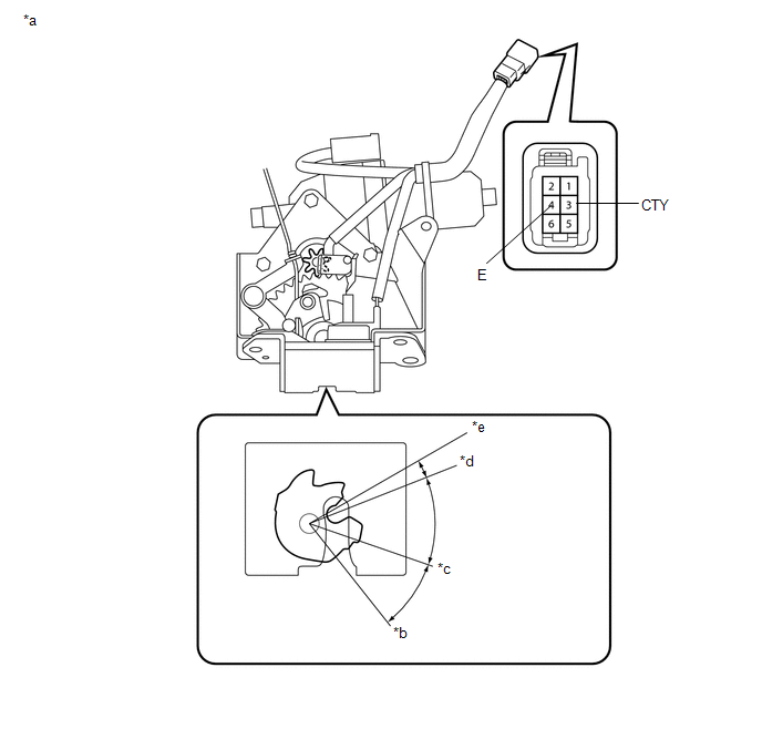
Text in Illustration
|
*a |
Component without harness connected (Back Door Lock Assembly) |
*b |
Open-latch |
|
*c |
Half-latch |
*d |
Full-latch |
|
*e |
Over-latch |
- |
- |
(1) Remove the back door lock assembly (See page
![2016 - 2020 MY Sienna [12/2015 - ]; DOOR LOCK: BACK DOOR LOCK: REMOVAL](/t3Portal/stylegraphics/info.gif) ).
).
(2) Measure the resistance according to the value(s) in the table below.
Standard Resistance:
|
Tester Connection |
Condition |
Specified Condition |
|---|---|---|
|
3 (CTY) - 4 (E) |
Open-latch |
Below 1 Ω |
|
Half-latch |
Below 1 Ω |
|
|
Full-latch |
10 kΩ or higher |
|
|
Over-latch |
10 kΩ or higher |
(3) Reinstall the back door lock assembly.
| NG |
|
|
|
8. |
CHECK HARNESS AND CONNECTOR (BACK DOOR LOCK - MAIN BODY ECU) |
(a) w/o Power Back Door
(1) Disconnect the D13 main body ECU connector.
(2) Disconnect the W12 back door lock assembly connector.
(3) Measure the resistance according to the value(s) in the table below.
Standard Resistance:
|
Tester Connection |
Condition |
Specified Condition |
|---|---|---|
|
D13-19 (BCTY) - W12-3 (D+) |
Always |
Below 1 Ω |
|
D13-19 (BCTY) - Body ground |
Always |
10 kΩ or higher |
|
W12-1 (ACT-) - Body ground |
Always |
Below 1 Ω |
(4) Reconnect the back door lock assembly connector.
(5) Reconnect the main body ECU connector.
(b) w/ Power Back Door
(1) Disconnect the D13 main body ECU connector.
(2) Disconnect the W11 back door lock assembly connector.
(3) Measure the resistance according to the value(s) in the table below.
Standard Resistance:
|
Tester Connection |
Condition |
Specified Condition |
|---|---|---|
|
D13-9 (BCTY) - W11-3 (CTY) |
Always |
Below 1 Ω |
|
D13-9 (BCTY) - Body ground |
Always |
10 kΩ or higher |
|
W11-4 (E)- Body ground |
Always |
Below 1 Ω |
(4) Reconnect the back door lock assembly connector.
(5) Reconnect the main body ECU connector.
| OK |
|
| NG |
|
REPAIR OR REPLACE HARNESS OR CONNECTOR |
|
|
|